Port Dinllaen
by tynewydd » Sun May 11, 2014 11:05 am
A scheme late in planning (very) that has 4 stations centered around this big one -> Port Dinllaen. Advice/brickbats please!
I have been working on this whole plan for over 18 months so far, but I have begun to notice that this particular “railway that could have been” has started to become quite popular of late – see, for example, the latest RM. Where my ideas differ is perhaps that I have taken things further and imagined PD as a terminus junction between the GWR/LNER and LMS – all drawn by the lure of a second route to Dublin. This leads to a boundary terminus ala Bath Green Park but MR/ER/GWR in the period modelled – circa 1960. The imaginary “faction” shenanigans to get that to happen are set forth in this document which also contains ideas about typical train movements at PD.
The track diagram – as far as I have got – is here. I took a late vintage Holyhead, foreshortened it, welded on a soupçon of Bath Green Park, completely altered the MPD and the local goods yard which is more Buckingham GCR… My abject apologies for the myriad mistakes of omission and commission I have made – all of which will certainly revolt you.
Questions –
- I’m having trouble with call-on signals – which will be needed for the station pilot to grab carriages from Pl1 and move them to Pl2 or Pl3 and for new locos to back down onto trains that are in Pl4. It seems likely that I will want to be able to call those engines out of MPD Out and hold them before they enter the Platforms – so that implies calling on over the Up and Down – which I suppose means a “normal” signal as well above each? In my current plan I have used a ground signal and a ground calling on subsidiary. But I have never seen one of the latter – although I have seen a picture of a ground distant. Do they always need to be post-mounted miniatures instead?
- The detailed trackplan of Holyhead I have is of a late vintage – since it was re-modelled in between about 1970 and 1980. There are a reasonable number of theater/indicators in that plan – but I don’t know what is typical for a 1960 period, and when to use a set of miniature arms and when a stack of ground signals instead.
- The necessary compression to get the station into 15′ length including a rapidly diverging “branch” has pushed the throat together quite a bit and led to several slips (although nothing as dense as Newcastle!) – but it also means that most signalling will have to be at the edge of the throat, I think. I do hanker after a gantry as marked – but it would mean that for some routes the signal would be over the center of the points or slip it controls – is that ever OK – or would you have to move it either further out (left) or further in (right) or have two gantries (or none)?
- Gantry sighting – the current gantry is maybe 140 scale feet from each of two road bridges. What would the plan be there – co-acting under-slung repeaters, perhaps? What is the standard on when they are required?
- When you have a boundary station – does the signalling type change abruptly as control of the metals changes over? I envisage that at one time there were two signalboxes, one of which controlled the GWR branch (still could be modelled as there, in fact). But even suppose they were rationalized into one – would we see LQ arms on the ex Cambria/GWR as whereas the rest is UQ with perhaps as an odd survivor or two of LQ MR days – like the famous advanced starter for Pl2 at Holyhead ?
Anyway, thanks so much for looking and I welcome any pointers you can give – however radical. The entire folder of stuff including the above am working on is here.
Adam Richards
PS You are all welcome to reuse any of the signal parts I have in the Illustrator file inside that folder. If there’s interest I can put them into a separate template file.
by Danny252 » Sun May 11, 2014 12:34 pm
tynewydd wrote:I’m having trouble with call-on signals – which will be needed for the station pilot to grab carriages from Pl1 and move them to Pl2 or Pl3 and for new locos to back down onto trains that are in Pl4. It seems likely that I will want to be able to call those engines out of MPD Out and hold them before they enter the Platforms – so that implies calling on over the Up and Down – which I suppose means a “normal” signal as well above each? In my current plan I have used a ground signal and a ground calling on subsidiary. But I have never seen one of the latter – although I have seen a picture of a ground distant. Do they always need to be post-mounted miniatures instead?
For your “ground distant”, all I can think of is that you’ve seen a yellow disc, which has an entirely different meaning to “distant”! However, you have used one correctly for the quarry headshunt.
Regarding shunting, ground/disc/shunting signals always act “calling on” – the same disc will clear whether the platform is empty or occupied, and it is the driver’s job to act accordingly. Only main running signals would require calling on arms, but even they can be dispensed with if Station Yard Working is in force.
The main site has a page on shunting signals, which you might find useful
When you have a boundary station – does the signalling type change abruptly as control of the metals changes over? I envisage that at one time there were two signalboxes, one of which controlled the GWR branch (still could be modelled as there, in fact). But even suppose they were rationalized into one – would we see LQ arms on the ex Cambria/GWR as whereas the rest is UQ with perhaps as an odd survivor or two of LQ MR days – like the famous advanced starter for Pl2 at Holyhead ?
I assume you mean a signalbox controlling the quarry access on the GWR single line? In that case, I would expect its signals to be LQ – after all, it’s the GWR who built and maintain them! In the case of rationalisation, I’d lean towards them having been replaced as part of an overall resignalling of the station in this example, but boxes inheriting signals of the “wrong” type wasn’t unheard of. Another consideration if you did this would be that each box would need its own distant signals (situated under the previous box’s starters for distances this short), which might get a bit messy in modelling terms!
The gantry seems fairly reasonable, but the space does sound quite limited!
by Richard Lemon » Sun May 11, 2014 2:38 pm
Adam,
Sorry to be a pedant, but should it not be called Porth Dinllaen or to be strictly correct “Porthdinllaen”?
Diolch!
Richard
by Mike Hodgson » Sun May 11, 2014 4:18 pm
My first comment would be that I don’t see the signalbox locations on the plan. With mechanical point operation, it has to be a fairly short distance from the points – there is a limitation on the length of rodding. By the 1970s/80s, power operation of the points would not be an issue, but if your box is the “original” one from an earlier date it would have been so constrained.
Given your hypothetical history, I agree I would have expected there to be at least two boxes, with the GWR tending to use the platforms on that side. This is unlikely to have been rationalised between the wars, but conceivable after nationalisation. I would expect that history to have set a precedent for platforms to have established a company bias to platform allocation and usage. The GWR box would be the smaller, and probably not large enough to handle the whole station; a single structure is therefore likely to be either a BR design or a resignalled LMS/LNER one depending which company got the job of signalling that joint operation.
I would also expect two goods sheds and engine sheds originally, a GWR one and a larger joint one. Perhaps your former GWR shed can be deemed to have been off-scene a little way off along that branch. The position of your yard is inappropriate for it to have been the LMS/LNE yard, as they would have to cross the GWR to reach it – it would have been on the other side or further back along that line.
The next thing that strikes me is that you have two roads crossing the station throat diagonally from bottom left to top right with double slips on the left hand road. The right hand of these roads does not serve the main platforms 2/3/4. Most modellers would have gone for only one road, both to minimise cost of pointwork and to save space – the trade-off might be against an extra carriage length in the platforms. Traditionally single slips were preferred, though double slips would not be unusual at a terminal station. Given that you have these two roads, I would expect those diamonds/slips to be arranged to permit parallel movements eg arrive platform 1 while departing Pl 3 on the main lines. This would involve more single slips but fewer double slips/diamonds (use the left hand diagonal for arrivals, the right hand one for departures). You have a third diagonal parallel to these two between Platforms 1/2. I don’t see what purpose this road serves – it does not seem to allow any more flexibility.
If I am reading it correctly, the highest signal on the 3-doll branch Home signal reads to Pl 4, implying this is the principal route. However as I said earlier I don’t think this would be the most usual main route from the Branch. I would have thought both originating and terminating branch trains would generally use Platform No 1 via the goods road you have labelled Gds In, certainly while you had a GWR box there. So I think your ringed arms are probably inappropriate, and also the trap, whilst correct for a goods road, would also not be there if it is a passenger route.
I would expect any trains from the branch requiring to work forward onto the main or vice versa would typically reverse in Pl 2/3. Terminating/originating trains on the Main would typically use 4/2/3 in order to avoid unnecessary traffic conflicts. If the Gds In road is only for goods use, any branch passenger working conflicts with any other movement except departure from Pl4 to Main.
The running signal and call-on protecting the crossover at the end of Pl4 seems unlikely (and not mirrored on Pl 1b for the run-round point there). I assume this crossover is for engine release (though you can’t use it while you have a goods on the Goods Out road). I would not normally expect a signal there. Instead I would expect the crossover to be locked normal when a train is arriving/departing Pl4, or perhaps a release to a ground frame working the crossover.
The quarry siding off the branch would probably be worked by a ground frame by the 70s/80s. Is the big X a public level crossing? This would probably have had a GWR gate keeper’s hut, as I doubt the GWR box could be right beside it and be within the limits for point rodding nearer the platforms. It might possibly have been be combined with Danny’s Quarry sidings box; your (demolished) former GWR engine shed might also be deemed to be close by, so it could even be a medium sized box with a goodly number of spare levers. By the 70s/80s this would have been reduced to a non-block post; the crossing might well have been converted to barriers.
I take it the two bridges are road over-bridges with their supporting pillars? These would undoubtedly give rise to sighting problems (especially all the pillars supporting the one across the platform ends), so you will need to consider signal heights and whether any banner repeaters are necessary. Look at it from a driver’s eye point of view – I doubt they would see signals on the gantry unless underslung.
Your gantry does seem to be in the right place for signalling purposes. Unfortunately for adequate sighting those signals probably want to be mounted on or right up against the road bridges, but unfortunately that would put them on the wrong side of the points they apply to. The usual way round this problem is to move the junction signals further back. In this case that would mean the platform starters would all be junction signals clearing only when the route is set right through the station throat. It makes the interlocking more difficult but I suppose you can accept that! As a modeler I suppose your decision is whether you want the bridge or a gantry
The cattle dock would have become redundant by the 1970s, though the siding could remain useful for eg engineer’s stock.
by Mike Hodgson » Sun May 11, 2014 4:31 pm
Richard Lemon wrote:
Adam,
Sorry to be a pedant, but should it not be called Porth Dinllaen or to be strictly correct “Porthdinllaen”?
Diolch!
Richard
Nonsense! It is well known that the railways were built and run by Englishmen who could neither spell nor pronounce Welsh names, (and who weren’t that hot with English names either).
This message was posted from Drenewydd Gelli Farch, a place with two corrections to its spelling on the village name-board! GWR Hall class 4967 only ever carried the English name of the local “big house”.
by Richard Lemon » Sun May 11, 2014 5:19 pm
Ah, but Porth Dinllaen is the English version!!!!!!!
Anyway, it is a lovely place, great for Seals – but that is not relevant to the signalling!
Richard
by tynewydd » Mon May 12, 2014 12:00 am
Danny252 wrote:
For your “ground distant”, all I can think of is that you’ve seen a yellow disc, which has an entirely different meaning to “distant”! However, you have used one correctly for the quarry headshunt.
This is the one I meant – from this sites S&T forum – http://forum.signalbox.org/viewtopic.php?f=6&t=3699#p43554 – I assume the lower disc is supposed to be a distant because of the black field and the yellow banner with fishtail and black chevron.
Your note about ground signals reading as calling-on themselves is very helpful and explains why I never saw such a picture of those.
Danny252 wrote: I assume you mean a signalbox controlling the quarry access on the GWR single line? In that case, I would expect its signals to be LQ – after all, it’s the GWR who built and maintain them! In the case of rationalisation, I’d lean towards them having been replaced as part of an overall resignalling of the station in this example, but boxes inheriting signals of the “wrong” type wasn’t unheard of. Another consideration if you did this would be that each box would need its own distant signals (situated under the previous box’s starters for distances this short), which might get a bit messy in modelling terms!
I actually meant a box positioned right at the end of the GWR line because I assume it would be handy for token exchange – needed for a single line – and give visibility around the tight curve.
As a prototype note – in Holyhead before rationalization, according to “Chester to HolyHead Railway” by Anderson and Fox there were at least two boxes – No 1 (40 levers) controlled the end of the throat and No 2 (74 levers) the Platforms. I say at least because think there was a No 3 that controlled the mail pier at one point as well. Anyway, arriving trains passed 3 distants, one for No 1 and two positioned under homes both of which had levers from No 2 box. The rear one was an “outer distant” perhaps? I know there was an accident at HH where one train rear-ended another in Platform 1 and excessive speed down the falling gradient was seen to be a contributory cause – having multiple distants that could be pulled off leading to terminal platforms might not have helped either….
Departing trains, however, did not see any distant as they passed between No 2 and No 1 control. I imagine this implies that the Up Main block post was owned by No 1 and the platform starters only gave clearance to it.
Danny522 wrote:The gantry seems fairly reasonable, but the space does sound quite limited!
I’ll wait to build consensus. I am half-thinking that moving that gantry to just behind the left-hand bridge might clear things up a bit, with Up direction signals above and mounting under it any signals needed in the Down direction so they are visible under that bridge.
Thanks again,
Adam
by Pete2320 » Mon May 12, 2014 3:50 am
tynewydd wrote: This is the one I meant – from this sites S&T forum – viewtopic.php?f=6&t=3699#p43554 – I assume the lower disc is supposed to be a distant because of the black field and the yellow banner with fishtail and black chevron.
Ah, that one almost certainly is a distant but is also a red herring! Note that it stands next to a miniature railway so is probably acting as a running signal.
by Danny252 » Mon May 12, 2014 12:35 pm
Pete2320 wrote: tynewydd wrote: This is the one I meant – from this sites S&T forum – viewtopic.php?f=6&t=3699#p43554 – I assume the lower disc is supposed to be a distant because of the black field and the yellow banner with fishtail and black chevron.
Ah, that one almost certainly is a distant but is also a red herring! Note that it stands next to a miniature railway so is probably acting as a running signal.Pete
I think it’s worth perusing this forum with a bit of caution – a lot of the things you’ll find illustrated are here because they’re the exact opposite of normal practise!
by JRB » Mon May 12, 2014 1:49 pm
At least Port Dinllaen is getting more thoughtful planning than a lot of full size installations.
by tynewydd » Mon May 12, 2014 3:00 pm
Mike Hodgson wrote:My first comment would be that I don’t see the signalbox locations on the plan.
Right because I was wrestling with it. The easiest place (space-wise) for a single rationalized box would be between the two bridges on the MPD side.
Mike Hodgson wrote: I would also expect two goods sheds and engine sheds originally, a GWR one and a larger joint one.
Well I have the two sheds in the MPD – ala BGP. I might be able to squeeze a second shed into the good yard, but I can’t get another yard into the other side of the tracks. In my notes you may see that I have provisioned a LMS bypass for freight that avoids PD all together. Perhaps I can plead that the width of the PD site is restricted by geography and the Admiralty to a narrow strip and so all goods facilities had to be shared. In general, I wonder if we should see the GWR as a late-comer, forced to put up with whatever arrangements the existing owners can be bothered to provide.
Mike Hodgson wrote:The next thing that strikes me is that you have two roads crossing the station throat diagonally from bottom left to top right with double slips on the left hand road. The right hand of these roads does not serve the main platforms 2/3/4.
Right – the HH prototype has semi-dedicated engine release road. It doesn’t serve 2/3 because they are departure only. The reason for that is that the boats arrive adjacent to Pl 2; discharge and then move around to Pl1 to onboard. It’s other function was that it has once had an additional slip coming from the adjacent goods line which led across to the Gds Out side. This is a place where Peco’s range of points is deficient!
Mike Hodgson wrote:Given that you have these two roads, I would expect those diamonds/slips to be arranged to permit parallel movements eg arrive platform 1 while departing Pl 3 on the main lines.
Yes – I see the reason is that I have managed to attach the Up and Down shifted one over from HH somehow. The Gds In was the Dwn, the Dwn was the Up and the current Dwn was a Up/Down Passenger (once a Down Gds). Hmm – time for a rethink on that alignment.
Mike Hodgson wrote:If I am reading it correctly, the highest signal on the 3-doll branch Home signal reads to Pl 4, implying this is the principal route.
Yes – I agree basically – I had intended for Pl1 to be the termination point of most inbound regardless of branch or mainline. I was thinking of the “through” trains that would be say Cardiff to Manchester. Those have to “cross-over” in one direction or other regardless of which way is “normal”. Currently only Pl4 has the capacity for double-headed trains to arrive and have a change of motive power as well.
Mike Hodgson wrote:I would expect any trains from the branch requiring to work forward onto the main or vice versa would typically reverse in Pl 2/3. Terminating/originating trains on the Main would typically use 4/2/3 in order to avoid unnecessary traffic conflicts. If the Gds In road is only for goods use, any branch passenger working conflicts with any other movement except departure from Pl4 to Main.
Right – consequence of above shift of exit tracks. But we also have to consider the effect of the boats. Pl4 would be the least favored of the platforms for arriving OR departing boat passengers (further to walk, no overhead roof – important in North West Wales!). Therefore I can see an argument that when there are competing services for London and the owners of the station are LMS/LNE, they might consign the GW trains to that spot out of spite.
Mike Hodgson wrote:The running signal and call-on protecting the crossover at the end of Pl4 seems unlikely (and not mirrored on Pl 1b for the run-round point there). I assume this crossover is for engine release (though you can’t use it while you have a goods on the Goods Out road). I would not normally expect a signal there. Instead I would expect the crossover to be locked normal when a train is arriving/departing Pl4, or perhaps a release to a ground frame working the crossover.
It is odd, but it’s a feature of the HH plan post re-org. The main signal seems to have no lever (fixed?) and the calling-on is operated by lever 3 of a GF. The other two leavers are #1 “Release” and #2 the crossover points. I guess Release was actually to lock the associated signals in the box?
Mike Hodgson wrote:The quarry siding off the branch would probably be worked by a ground frame by the 70s/80s. Is the big X a public level crossing?
No sorry – that was my ham-fisted way of acceding to the strictures of the plan posting rules – its supposed to be two opposing arrows showing bidirectional working. Then the track got extended…
Mike Hodgson wrote:I take it the two bridges are road over-bridges with their supporting pillars?
Yes. I agree about the sighting. I may be able to nudge the LHS bridge left, however.
Mike Hodgson wrote:The cattle dock would have become redundant by the 1970s, though the siding could remain useful for eg engineer’s stock.
Yup – that’s another reason why I’m early 60s. HH lost all its cattle traffic only after the Menai Bridge fire in 1970.
Thanks again for the help, I’ll cogitate on the alignment of the entry tracks and update.
Regards,
Adam
by Mike Hodgson » Mon May 12, 2014 5:40 pm
Pete2320 wrote: Ah, that one almost certainly is a distant but is also a red herring! Note that it stands next to a miniature railway so is probably acting as a running signal.
Pete
Correct.
Dave posted it to illustrate his slotting arrangement.
by Mike Hodgson » Mon May 12, 2014 7:50 pm
tynewydd wrote: It is odd, but it’s a feature of the HH plan post re-org. The main signal seems to have no lever (fixed?) and the calling-on is operated by lever 3 of a GF. The other two leavers are #1 “Release” and #2 the crossover points. I guess Release was actually to lock the associated signals in the box?
Yes, the main signal would have been fixed at danger, as there is no running movement beyond it. You have to have a main signal there because it’s not allowed to have the previous running signal leading to only a shunt signal. The GF and the signal box would lock each other out, ie the points must be normal whilst a train is arriving or departing, and the signal levers for such moves would have to be normal before the GF could be worked. The distance from the box (point rodding run) and lack of view would make it much easier to work this way than trying to work the points from the box.
The 1965 Holyhead accident was put down to a misjudgment on the driver’s part, because the call-on authorises him to enter the occupied platform, prepared to stop short of any obstruction, and this he patently failed to do. He fully expected to find the train there, but evidently expected it to be shorter/nearer the stops and his speed was only slightly excessive.
The signalmen didn’t escape comment either though – they were regularly failing to apply rule 39(a), clearing the outer home signal prematurely when the inner home was at danger and 44(b) clearing the call-on before the train had come completely to a stand, although in mitigation they were not in a position to know whether the train had stopped because they did not have a proper view. I don’t think the distants came into it. It used to be normal practice to clear distants into terminal platforms, but only when the road was clear to the stops (it wasn’t, and the distant was at caution)
by davidwoodcock » Mon May 12, 2014 9:55 pm
Mike Hodgson wrote: Yes, the main signal would have been fixed at danger, as there is no running movement beyond it. You have to have a main signal there because it’s not allowed to have the previous running signal leading to only a shunt signal.
Wasn’t the use of fixed semaphore stop signals a comparatively recent (say 1960s) feature that grew out of the introduction of fixed red+subsidiary colour light signals (which were definitely in use by 1960)?
I would have thought that earlier just a small-arm subsidiary signal would have been used, being cleared to permit the shunt movement instead of the dolly later provided. I seem to remember that Holyhead had somewhere in its layout the shortest arm LQ LNWR signal that I have ever seen which had just this sort of function.
by tynewydd » Tue May 13, 2014 7:16 am
Mike Hodgson wrote: Yes, the main signal would have been fixed at danger, as there is no running movement beyond it. You have to have a main signal there because it’s not allowed to have the previous running signal leading to only a shunt signal.
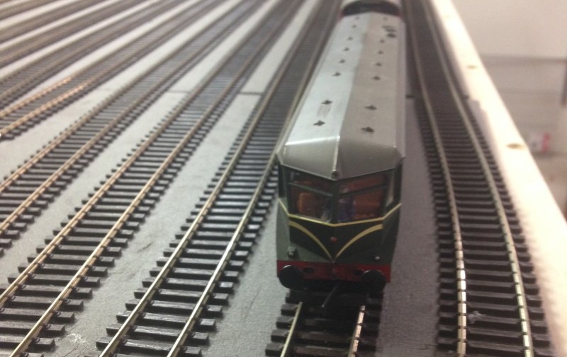
The signal in question surrounded by an very ornate fence!
Seems the photo is relatively recent based on that illuminated sign. This also gives you an idea of the perils of passengers on this platform in inclement weather with an easterly wind.
Adam
by kbarber » Tue May 13, 2014 11:05 am
Hello Adam, I hope you’ll indulge a little rather radical thinking to see if anything comes of it?
Historically, I’d have been just a little surprised if the Cambrian had had such a welcome that it was invited to use the NWIR station, particularly as the site was cramped & difficult and there was no suitable platform on its side of the station. So was there initially a CR station somewhere in the vicinity of the carriage sidings, or even the goods in road/cattle dock? If so, there might be remains that were adapted for other uses once the interloper had finally been allowed to join in the big boys’ game. Another place the CR station might have ended up was down the breakwater beyond the NWIR platform 1, approached more-or-less along the line of the Run Round or one of the carriage sidings. (The big boys might have considered that a suitable place of outer darkness for the interloper – not always a minor consideration.) That would mean separate station buildings to a different design alongside 1b. It would also almost certainly mean the CR had to build two signalboxes, one in the vicinity of the main station throat to work the connections with the NWIR station and another for the points between their platform and run round roads. At that stage there would be no connection between 1a nd 1b, and probably not even a continuous platform there. (A lot of money for minimal facilities, but why should that bother the incumbents who would be making the rules?) Eventually, of course, sanity prevailed and the platform lines were linked (a la Manchester Victoria/Manchester Exchange) but leaving the second approach to 1b along the RR. (All that certainly fits with your suggestion in your post of 3pm yesterday that the GW was made to put up with what the incumbent could be bothered to provide, except that all they provided was the most awkwardly constrained bit of land they could get away with leaving the CR/GW to fit in what they could.) It also perhaps explains why the goods yard has to be accessed across the GW approach, but it’s likely to mean that there is only one access which (when built) would’ve been as close to the signalboxes as possible – there would have had to be a CR box around the east end of the throat and a NWIR one not too far from it, with complications of bolt releases between them to give what would effectively have been dual control of several sets of points.
Like Mike I’d expect the GW to have a separate MPD. I’m not sure BGP is an appropriate reference here, I guess the sheds there were MR and S&D, in which case you have a degree of common ownership that wouldn’t exist at PD. The branch sounds a very reasonable place to put a GW shed and I’m afraid my instinct is that it would fit rather nicely where you have the quarry. That would certainly add to the interest of through trains, with either the inward or forward loco having to cross the whole layout from the branch to P4 or Goods Out road. If the site is actually that physically constrained (a wall of granite so it has to be a quarry not a shed) I’d be looking to put the GW MPD offstage further along the branch, probably with a box controlling access from the single line. Initially there would’ve been some sort of staff or token working, of course, but the buildup of traffic might have led to the section being controlled just by signals. I’m not sure whether Direction Lever might have been considered appropriate in this situation (perhaps JRB would be able to advise what the criteria were for that to be an acceptable method of working). But if not the GW did use its own design of single line lock-&-block instruments (several sections in the Malvern area) and that might have been very suitable for a situation where there were frequent locos on & off shed to be fitted between the procession of holiday trains. Any kind of physical authority for the single line would be a major pain in the proverbial in that situation! Assistance up the bank needs to be provided for as well. If the bank begins very close to PD I’d imagine passenger trains to the GW would just be double-headed. The alternative is that they have to stop in or just beyond the throat to take their banker or that the banker has to join them in the platform; I don’t imagine the inward engine would be used as a banking engine, although I’m sure there were places where that did happen. If the bank started further out, the stop might well be at the GW shed but that, of course, would be offstage so wouldn’t offer what you seek.
So what begins to crystallise in my mind is a layout where the main MR/GC lines pretty much run straight into P1 and P2 with the main diagonal connection(s) then running top left – bottom right to P4. The CR/GW would then enter pretty much along the Goods In which would line up with the RR to give access to 1b. That would mean running signals rather than shunts – and perhaps additional calling on signals as well – on & off the Run Round (together with releasing arrangements at the far end of 1b that would mirror those you provide for P4). But it’s quite likely there would be no facing connection from the down LM/ER to the GW approach, although there might be an up direction connection from the GW approach to the up LM/ER. Connections to & from the shed(s) and goods facilities would then need to be added according to need. The highest doll on the branch home bracket would then be an additional leftmost one reading along the GW approach (present Goods In) towards 1b.
The original layout would probaby have had four boxes, the two CR/GW ones already mentioned (with the station end box having no connections to the NWIR lines) plus the main NWIR box controlling the throat and a secondary one at the station that would certainly be needed to work the P2/P3 connection and signals at least (it might also, as at Broad Street, work platform end signals both in & out and would undoubtedly have some control over the run round connections off 1 (later 1a) and 4. I say this because pointwork would have been clustered close to the locations of these boxes and that configuration might not change a great deal with the resignalling. (It rather depends just how much disruption the various railway/regional authorities were prepared to countenance when the resignalling took place.) Even in BR days there were intense regional rivalries and, given the joint nature of the operation that would set it apart from the owning railways, it’s quite possible there would be some staff at PD who still considered themselves NWIR as late as the 1980s!
So far as the run rounds are concerned, I suspect the HH P3 layout dates from the 1970s remodelling. In the 1960s or earlier I’d expect to see your P4 run round controlled by a ground frame released from the box, with drivers trusted to stop clear of the crossover they needed to use. P1 would be rather more interesting. My surmise would be that when the 1a – 1b connection was put in, the GW Station box would be given a slot on the main running signals controlling the entrance to 1a so that a train wasn’t admitted on a main aspect while the crossover was reversed against it. (Those signals would probably also be given warning arms, again with a slot from the GW station box, so a train could still be let in if the GW crossover was in use.) The discs at the crossover on the P1 line would be full-sized arms, with the 1b starter probably being a bracket to allow departures via 1a or the GW approach and both it and the 1a arrival signal having calling on arms so run rounds and shunts could take place with a train or vehicles in 1a or 1b. These signals and the crossover would all be worked by the GW station box (which might well need reframing to accommodate the additional functions and would end up with some kind of block working both to the main GW box along the GW approach and to the NWIR box along P1). All these signals would almost certainly be retained on resignalling with the crossover motorised and a full complement of warning and calling on arms – that would be the only way to achieve the necessary flexibility.
If you find yourself needing to economise on levers (the new box will be a big job!) it might be useful to surmise that the resignalling was an LMR job. The LM was big on signals selected by points and theatre-type indicators would fit that idea very well (though I fear you’d need to lose the branch bracket). But the ER might well have gone for an arm for each route at the inner home signals, hence a nice bracket at the NWIR inner home as well. Whether the discs would have route indicators (likely to be stencil type rather than theatre type) is uncertain. There are probably people here better able then me to say, but I have a suspicion the LM would have been more likely to use them than the (LN)ER.
I hope that little lot doesn’t upset too many apple carts; better yet, perhaps it will start you thinking even more about what is being provided. This looks like a good scheme and I’d love to see what it looks like when it’s built. If the whole station throat had been heavily remodelled your plan, subject to some of the comments others have made, might well have been the outcome so it could still be one to go with. But I’d suggest you need to look at P1 and P4 differently (hopefully my thoughts will be useful there).
by Pete2320 » Tue May 13, 2014 12:00 pm
davidwoodcock wrote:Mike Hodgson wrote: Yes, the main signal would have been fixed at danger, as there is no running movement beyond it. You have to have a main signal there because it’s not allowed to have the previous running signal leading to only a shunt signal.
Wasn’t the use of fixed semaphore stop signals a comparatively recent (say 1960s) feature that grew out of the introduction of fixed red+subsidiary colour light signals (which were definitely in use by 1960)?
I’d certainly go along with that
also wrote:I would have thought that earlier just a small-arm subsidiary signal would have been used, being cleared to permit the shunt movement instead of the dolly later provided.
Or a full size arm, cleared for what we would nowadays consider a subsidiary movement.
and also wrote:I seem to remember that Holyhead had somewhere in its layout the shortest arm LQ LNWR signal that I have ever seen which had just this sort of function.
Not the one I remember. That was a fully fledged running signal (platform starter?). The short arm was to give clearance to an adjoining line.
Pete
by Chris Osment » Tue May 13, 2014 12:18 pm>> I’m not sure BGP is an appropriate reference here, I guess the sheds there were MR and S&D, in which case you have a degree of common ownership that wouldn’t exist at PD….
Indeed, that was the case
by kbarber » Tue May 13, 2014 5:41 pm
I’m afraid I’ve had another thought.
1897 is rather early for the line from Aynho; the GW & GC Joint from Northolt Jc to Ashendon Jc didn’t open until 1906 and Marylebone itself wasn’t opened until 1899. So it would fit known railway history better if the Irish Extension opened sometime around 1908 – 10.
The date matters. Obviously the Irish Extension would bring considerable new traffic to the original B&I/NWIR lines, which might well need quite a bit of resignalling to meet this new demand. That, of course, was the period that the GCR was installing a good deal of power signalling worked by BPRS draw-slide frames. (See http://www.signalbox.org/gallery/e/hydejcn.php and http://www.signalbox.org/gallery/e/receptionsidings.php for examples.) So what’s the likelihood that the Irish Extension was built with power signalling from the start and that the original NWIR was resignalled at the same time to cope with the extra traffic?
The GCR’s Signal Engineer at the time was A F Bound, who had worked on the LSWR LP pneumatic signalling briefly in 1903 while employed by BPRS; he would have seen something of that company’s automatic signalling between Woking and Basingstoke and it really isn’t too much of a stretch to think he would have tried the same thing on the new line. Automatic signalling would have had considerable advantages on the original B&I line too, as it would allow far greater traffic to be worked by less signalboxes, perhaps no small consideration in the sparsely populated countryside of Snowdonia. It would also allow shorter sections on the fearsome climb from Bangor through Bethesda and on to Llyn Ogwen. We know that Bound was impressed by US practice so it’s also likely that any sidings provided on the new and resignalled lines would be worked by ground frames interlocked with the new signals, further reducing the number of signalboxes required.
Port Dinllaen would probably need a degree of resignalling too, after all it would (hopefully) become the terminus of a much increased traffic from London and the Midlands. (So would Pont Llyni Junction, for similar reasons.) Again, it’s not unlikely that a power scheme would be chosen. Although the new system allowed automatic signalling in open country, traditional block working tended to be retained where boxes were close together (as seems likely in the immediate vicinity of PD, where there’s likely to be further yards, sidings, interchanges with NG lines from the slate quarries, etc).
So we can postulate a full resignalling taking place in about 1907, with provision of every modern appliance and a generous track layout in anticipation of the forthcoming traffic. Perhaps this was the time, too, when the Cambrian and the GC & Midland Joint integrated their two stations (as I mentioned in my previous post). That would have made things a lot easier for all concerned as it would allow the CR to close both their boxes (worth a contribution to the cost of resignalling) and improve the working of the station no end.
So far as the signalbox building was concerned, I have an idea that on joint lines it wasn’t uncommon for one company to have responsibility for buildings while the other dealt with signalling equipment (or some other such split). So we could well have a (largish) Midland Railway box to house the draw-slide frame, which would be fairly visible through the windows.
During the decades of financial stringency that followed the Great War and extended into the 1970s and ’80s, it is unlikely that PD would have been high on the list for resignalling. After all, the line was already fairly economical to work with its long stretches of automatic signalling, and power signalling at the main traffic nodes also kept the staffing requirement lower than at manually-worked stations. So the signalling at the date of the layout would be likely to consist of a mix of GCR lower quadrants and a few LNER upper quadrants worked from the power frame in a good sized MR box (possibly with its lower parts protected by a thick brick blast wall).
How does that little lot sound?
by Pete2320 » Wed May 14, 2014 4:13 am
kbarber wrote:How does that little lot sound?
I love it
by tynewydd » Wed May 14, 2014 5:14 am
kbarber wrote:Hello Adam, I hope you’ll indulge a little rather radical thinking to see if anything comes of it?
Sure – the great thing about the current state is that apart form the outline and overall 21’x12′ (with one side open) nothing is yet fixed. This is – as I can see from the inventiveness being shown on this board – a good thing!
kbarber wrote: Eventually, of course, sanity prevailed and the platform lines were linked (a la Manchester Victoria/Manchester Exchange) but leaving the second approach to 1b along the RR.
Ok – following along, so that would mean adding a linkage between the Gds In and the Pl1 RR, allowing a shorter -possibly 2 coach train stopping train to approach and depart 1b directly for the branch. Interesting.
Just as a historical note, the layout at HH had such a secondary station at the mail pier reached roughly along that approach. The idea, I think, was for the mail packets to be closer to Dublin by being directly in the outer harbour. Kind of the opposite reason but similar trackwork.
I guess from all these comments that the “through express” would have been welcome to arrive and depart from Pl4? After all, at least on departure to Caernarvon/Manchester it would be on the down LMS/LNE side. As I have half-drawn it now there is a sweeping curve leading from platform 4 that points directly to the branch… This enabled me to have the branch not have to have a tighter curve but start the main exit curve earlier allowing the branch
kbarber wrote:Like Mike I’d expect the GW to have a separate MPD. The branch sounds a very reasonable place to put a GW shed and I’m afraid my instinct is that it would fit rather nicely where you have the quarry.
So my problem with this is not the shed per se, substituting for a quarry is doable but the need to provision (presumably) a second turn-table. I don’t have that room, or rather, I don’t have room for more than a turntable or a shed. There is a rising branch line hidden behind and ~6″ below that quarry right now that is connecting PLJ to Nantlle. And then the wall…
In the part of the plan you can’t yet see, the MPD is constructed in the “efficient” large scale manner suggested by Harry and the late Ivor C. Marshall but with a second shed hanging off the turntable (and so gaining the advantage of a 90 degree turn “for free”. I know that in BR days post war there was a move to upgrade sheds to make them less labor intensive. BGP, for example, seemed to have been rationalized versus the two different sheds with different turntables which I think existed prior.
kbarber wrote:That would certainly add to the interest of through trains, with either the inward or forward loco having to cross the whole layout from the branch to P4 or Goods Out road.
Yup – is it acceptable to have a single turntable and “efficient” facilities so locos can be fed and watered on the LMS/LNE but have them cross over to the “other side” to be merely stabled in the old GW shed? In particular bankers, and other WR stuff, for example?
kbarber wrote:I’m not sure whether Direction Lever might have been considered appropriate in this situation
I see I have some reading to do!
kbarber wrote:Assistance up the bank needs to be provided for as well. If the bank begins very close to PD I’d imagine passenger trains to the GW would just be double-headed. The alternative is that they have to stop in or just beyond the throat to take their banker or that the banker has to join them in the platform; I don’t imagine the inward engine would be used as a banking engine, although I’m sure there were places where that did happen. If the bank started further out, the stop might well be at the GW shed but that, of course, would be offstage so wouldn’t offer what you seek.
Agree on double-heading for all important passenger trains. If I change the gradients a bit, I can make the first part to beyond the “shed” be pretty flat. That way there could be signals for bankers from the shed. I assume that means a calling on signal so the banker can approach? The bank ends at Tan-Y-Graig which has a double-ended central road a la Evercreech for banking engines that arrived as LEs to wait for custom/run back to HH. But that’s a later topic.
kbarber wrote:So what begins to crystallise in my mind is a layout where the main MR/GC lines pretty much run straight into P1 and P2 with the main diagonal connection(s) then running top left – bottom right to P4. The CR/GW would then enter pretty much along the Goods In which would line up with the RR to give access to 1b.
Amazingly that was what I was sketching out in response to John’s observation about the misalignment of the main roads. I hadn’t added in the idea of 1b access though.
kbarber wrote:That would mean running signals rather than shunts – and perhaps additional calling on signals as well – on & off the Run Round (together with releasing arrangements at the far end of 1b that would mirror those you provide for P4). But it’s quite likely there would be no facing connection from the down LM/ER to the GW approach, although there might be an up direction connection from the GW approach to the up LM/ER. Connections to & from the shed(s) and goods facilities would then need to be added according to need. The highest doll on the branch home bracket would then be an additional leftmost one reading along the GW approach (present Goods In) towards 1b.
Yup – I’ll try and get the roads right first and then I’ll take all the comments about re-signaling in the light of the new plan. I am drawing in XTRKCAD in parallel because you can make vast changes easily in Illustrator that you have no ability to actually build…
kbarber wrote:I hope that little lot doesn’t upset too many apple carts.
No – a little apple-cart upsetting is exactly why this is a valuable forum. Plus its only by this type of in depth discussion that one can learn anything useful.
I even like the comments about the name – it mirrors the comments between me and my Da about the same subject. As a 50% Welshman myself, but some one with only enough knowledge of the “Language of Heaven” to understand when I am being told not to park somewhere rather than I am stupid to try (Dim Parcio), or that a “Little House” (Ty Bach) might be something smelly in addition to diminutive, he (someone who is fluent) had a few choice words for the Victorians and their cluelessness.
Thanks again,
Adam
by tynewydd » Wed May 14, 2014 6:07 am
kbarber wrote:I’m afraid I’ve had another thought.
1897 is rather early for the line from Aynho; the GW & GC Joint from Northolt Jc to Ashendon Jc didn’t open until 1906 and Marylebone itself wasn’t opened until 1899. So it would fit known railway history better if the Irish Extension opened sometime around 1908 – 10.
Quite right – faux history rewritten! Makes one feel almost Soviet…
I like the overall thinking, if this proves out then the Buckingham GCR (àla Denny) lineage of the scheme will have more than a virtual “tip o’ the hat” to the Master. I get the key advantages, I think. You have bigger, fewer, boxes and you have economy in levers because you can do more with less – which makes running the show easier – with things like automatically resetting the signals to danger. And because you have older GC LQ and newer LNE UQ, and remaining GW LQ possibilities you have lots of potential variety. But still you get “traditional” block working because of close distances in this case.
You mention a “blast wall” around the lower part of the signalbox because of the presence of compressed air inside it, or as a protection for the sensitive equipment there against the gentle ministrations of the Luftwaffe?
kbarber wrote:How does that little lot sound?
Hmm. “Little” or “lot”? Surely the combo is an oxymoron!! You certainly have given me some good things to ponder – let me see if I can get a workable trackplan as amended to start with.
Adam
by kbarber » Wed May 14, 2014 7:47 am
tynewydd wrote:kbarber wrote:I’m afraid I’ve had another thought.
1897 is rather early for the line from Aynho; the GW & GC Joint from Northolt Jc to Ashendon Jc didn’t open until 1906 and Marylebone itself wasn’t opened until 1899. So it would fit known railway history better if the Irish Extension opened sometime around 1908 – 10.
Quite right – faux history rewritten! Makes one feel almost Soviet…
I like the overall thinking, if this proves out then the Buckingham GCR (àla Denny) lineage of the scheme will have more than a virtual “tip o’ the hat” to the Master. I get the key advantages, I think. You have bigger, fewer, boxes and you have economy in levers because you can do more with less – which makes running the show easier – with things like automatically resetting the signals to danger. And because you have older GC LQ and newer LNE UQ, and remaining GW LQ possibilities you have lots of potential variety. But still you get “traditional” block working because of close distances in this case.
The bigger, fewer boxes would only exist at principal locations. The other advantage is no boxes at all for long distances in open country and far smaller boxes (physically, at least) at junctions and suchlike places. And perhaps boxes open ‘as required’ (a few hours a day, Monday – Friday only) at mid-sized stations that warranted regular service of a goods yard. (Reading that, I hope I haven’t made the wrong assumption about what you’re saying… apologies if so.)
I think, if the scenario I painted for pre-WWI resignalling had taken place, it’s very unlikely there would have been any GW signals left at PD Station itself. If the MPD were far enough away to warrant its own box it would have GW lower quadrants (or possibly even some Cambrian LQs – I wonder how long some of them survived?) but the GC would’ve replaced everything worked by the new power frame.
tynewydd wrote:You mention a “blast wall” around the lower part of the signalbox because of the presence of compressed air inside it, or as a protection for the sensitive equipment there against the gentle ministrations of the Luftwaffe?
Reception Sidings (as linked to) had one, and one around the compressor house too. Yes, it was intended to inhibit Herr Hitler’s dislike of fully-signalled stations, hence not unusual to find it was both rather heavy and very crudely built. At Crewe they took it further and built complete new signalboxes to an enhanced ARP specification but I’m not sure PD would’ve been considered to warrant such consideration. (Holyhead got no extra protection at all, although the fact it was a brick-built LMS design was surely relevant; I imagine it might have gained a blast wall had it been an all-wood structure.)
by kbarber » Wed May 14, 2014 8:29 am
tynewydd wrote:kbarber wrote:Eventually, of course, sanity prevailed and the platform lines were linked (a la Manchester Victoria/Manchester Exchange) but leaving the second approach to 1b along the RR.
Ok – following along, so that would mean adding a linkage between the Gds In and the Pl1 RR, allowing a shorter -possibly 2 coach train stopping train to approach and depart 1b directly for the branch. Interesting.
Actually I was thinking of 1b as a full-length platform, initially for the GW/Cambrian share of the mail traffic when their station was separate but obviously adding to the flexibility after integration.
tynewydd wrote:Just as a historical note, the layout at HH had such a secondary station at the mail pier reached roughly along that approach. The idea, I think, was for the mail packets to be closer to Dublin by being directly in the outer harbour. Kind of the opposite reason but similar trackwork.
I never knew that! Particularly interesting as my partner grew up just outside Holyhead and his nephew’s first steps on the railway included some time acting as booking boy in Holyhead box!
tynewydd wrote:I guess from all these comments that the “through express” would have been welcome to arrive and depart from Pl4? After all, at least on departure to Caernarvon/Manchester it would be on the down LMS/LNE side. As I have half-drawn it now there is a sweeping curve leading from platform 4 that points directly to the branch… This enabled me to have the branch not have to have a tighter curve but start the main exit curve earlier allowing the branch
If you’re saying what you suggested in your description of typical movements, then yes, that’s exactly what I think. Again, it will certainly add to the interest as every through express will have to cross the entire throat at some point in its passage, as will either the inward or outward loco(s). Keeps the signalman busy (or, as Flanders & Swann put it, “It all makes work for the working man to do”
tynewydd wrote:kbarber wrote:Like Mike I’d expect the GW to have a separate MPD. The branch sounds a very reasonable place to put a GW shed and I’m afraid my instinct is that it would fit rather nicely where you have the quarry.
So my problem with this is not the shed per se, substituting for a quarry is doable but the need to provision (presumably) a second turn-table. I don’t have that room, or rather, I don’t have room for more than a turntable or a shed. There is a rising branch line hidden behind and ~6″ below that quarry right now that is connecting PLJ to Nantlle. And then the wall…
Then perhaps the answer is an ‘offstage’ GW shed, with an advanced starter beyond the quarry siding to shorten the section a little further and some means of signals-only single line control to improve the throughput of traffic. I wonder if that might be supplemented by a loco holding siding (or even a small turnround servicing point, with water facilities and perhaps an ashpit) so GW locos waiting to take a through express forward could be brought down to the station before the train arrives from the Bangor direction?
tynewydd wrote:In the part of the plan you can’t yet see, the MPD is constructed in the “efficient” large scale manner suggested by Harry and the late Ivor C. Marshall but with a second shed hanging off the turntable (and so gaining the advantage of a 90 degree turn “for free”. I know that in BR days post war there was a move to upgrade sheds to make them less labor intensive. BGP, for example, seemed to have been rationalized versus the two different sheds with different turntables which I think existed prior.
kbarber wrote:That would certainly add to the interest of through trains, with either the inward or forward loco having to cross the whole layout from the branch to P4 or Goods Out road.
Yup – is it acceptable to have a single turntable and “efficient” facilities so locos can be fed and watered on the LMS/LNE but have them cross over to the “other side” to be merely stabled in the old GW shed? In particular bankers, and other WR stuff, for example?
Not so much whether it would be ‘acceptable’, more what the various companies (some at each others’ throats at times) would have provided in the dim & distant. In a situation such as this, the Cambrian would undoubtedly have built its own shed. In fact it would probably have started with a very small shed as close to the station as it could get, then built a ‘new’ shed further out when the original became impossibly small. (Sudden thought: the old Cambrian shed would almost certainly have become the location of the holding siding/turnround servicing point when the new shed was built.) Even in the late 1950s/early ’60s the GW Shed would be under entirely separate administration, with a BR shed code in the GW series (perhaps a sub-shed of Machynlleth) while the LM/ER shed would be in the LM series (possibly a sub-shed of Bangor but, for a location of this importance, more likely a principal shed in its own right). So whatever the LMS/LNE did to make their shed more efficient, the GW would be excluded from that particular party (and, being the GW, would definitely prefer it that way).
<snip>
tynewydd wrote:kbarber wrote:Assistance up the bank needs to be provided for as well. If the bank begins very close to PD I’d imagine passenger trains to the GW would just be double-headed. The alternative is that they have to stop in or just beyond the throat to take their banker or that the banker has to join them in the platform; I don’t imagine the inward engine would be used as a banking engine, although I’m sure there were places where that did happen. If the bank started further out, the stop might well be at the GW shed but that, of course, would be offstage so wouldn’t offer what you seek.
Agree on double-heading for all important passenger trains. If I change the gradients a bit, I can make the first part to beyond the “shed” be pretty flat. That way there could be signals for bankers from the shed. I assume that means a calling on signal so the banker can approach? The bank ends at Tan-Y-Graig which has a double-ended central road a la Evercreech for banking engines that arrived as LEs to wait for custom/run back to HH. But that’s a later topic.
It sounds as if you’re saying double-heading plus a banker as far as T-y-G? If that were the case I’d anticipate the banker being attached in the station. So the length of platform beyond the crossover in P4 needs to accommodate both inward engines and the banker. The turnround point might then also become the place where bank engine(s) get held waiting their next work, as well as a place to stow forward engines. The sequence of operations for a through express to the GW is then:
1: forward engines arrive from the GW shed and are signalled to the ‘Old Shed’ (as the loco turnround point is known to everyone at PD – its official name, as shown on the SB diagram, is probably ‘Loco Siding’);
2: bank engine(s) that have been waiting on the Old Shed drop down to the Goods Out;
3: when anything on the stops of P4 has removed itself, the bank engine runs through the crossover and settles itself right up against the stops on P4;
4: the through express arrives in P4 from the north;
5: the forward engine(s) is signalled from the Old Shed to P4 as soon as the road can be reset behind the arriving train;
6: the inward engine hooks off, runs forward towards the stops then back through the crossover onto the Goods Out and to the LM/ER shed;
7: the bank engine moves up to the train and prepares for departure.
All this suggests the P4 crossover being fully signalled (shunt signals would be OK) and worked from the box, rather than the kind of GF arrangement used at HH P3.
Of course it needs to be decided whether the bank engine is or is not coupled to the train (a Sectional Appendix entry will need to exist to authorise assistance in rear and coupling or not will be specified there).
Hope that offers something useful again!
Keith
by MRFS » Wed May 14, 2014 10:52 am
Cambrian LQs survived until the early 50s at Aberdovey for example.
by davidwoodcock » Wed May 14, 2014 1:30 pm
I just wonder whether the historical background might be a little more robust if, instead of the Midland and Great Central getting involved as individual companies, the acquisition had been made through the Cheshire Lines Committee, Britain’s biggest joint railway in which the Midland, GC and Great Northern were all equal partners. The facility to export coal from the Nottinghamshire and Yorkshire coalfields directly to Ireland might have been a powerful incentive for all three.
Incidentally, although the Cambrian Railways were grouped into the enlarged GWR in 1923, pre-grouping they had effectively been an associate of the LNWR rather than the GW.
by kbarber » Wed May 14, 2014 2:25 pm
davidwoodcock wrote:Incidentally, although the Cambrian Railways were grouped into the enlarged GWR in 1923, pre-grouping they had effectively been an associate of the LNWR rather than the GW.
All the more reason to think they wouldn’t have cosied up to the NWIR any more than they had to!
by tynewydd » Wed May 14, 2014 4:25 pm
kbarber wrote:Actually I was thinking of 1b as a full-length platform, initially for the GW/Cambrian share of the mail traffic when their station was separate but obviously adding to the flexibility after integration.
Nice but impractical I fear – there just isn’t room to extend the platform that much in a 21′ space with a passageway and a Tan-Y-Graig width before the other wall. I have got juice out of curving the platforms and having them slightly diagonal, but there are limits. However, if we consider that Platform 1b would have been a Victorian creation, coaches (and trains) were considerably shorter. I think the 60s local “sprinter” equivalents for the Canbrian coast could well be short trains, and we also have the possibility of auto-coaches or even early DMUs which get to block the engine release as well…
<snip>
kbarber wrote:Then perhaps the answer is an ‘offstage’ GW shed
Offstage is actually Pwhelli – a long way and uphill both ways for a turnaround. But – if the turntable could be a 55′ just like at Pwhelli (or 9″ in OO) then it looks like it would fit if I can exploit the V between branch and main. Big express Castles and so forth would have to slum it with the ER/MR first for turning but all the shorter stuff could do it Swindon fashion! I saw a reference to a 63′ Black 5 being turned once at Pwhelli – presumably you have to detach the tender and do it separately and then run around it with the engine. Not sure that is recommended as a standard practice, though. The design of my current MPD has a release line that bypasses the ash/coal and makes directly for the turntable and then there is a line back out again – so that actually makes sense from a “just need turning” POV.
kbarber wrote:It sounds as if you’re saying double-heading plus a banker as far as T-y-G?
No – technically that would be feasible with DCC – but at the cost of passenger accomodation again. We would end up with 4 coach trains using 2 Pacifics and a banker! I think double heading expresses, banking large passengers/any freight and having short stuff use powerful locomotives would be good. But I’ll certainly consider it and your notes on procedure are useful.
kbarber wrote:Of course it needs to be decided whether the bank engine is or is not coupled to the train (a Sectional Appendix entry will need to exist to authorise assistance in rear and coupling or not will be specified there).
If the bankers always run through to TYG – wouldn’t coupling be the way to go? Otherwise if the banked train comes to a stand at TYG home – the risk of a rear-end collision exists. If we don’t insist on then going to TYG and instead let the banker idle back to PD – the block will be occupied longer I expect – unless the banked section is really short when compared to the block.
kbarber wrote:Hope that offers something useful again!
Keith
Absolutely!
Adam
by kbarber » Wed May 14, 2014 9:31 pm
Apologies, Adam, for not quite getting how constrained your modelling site is. I realise one of the things you don’t have in your pages is a schematic diagram showing the bits you intend to model, the hidden storage and how they all connect up; I wonder if you might be able to put something up (even something rather crude) so we can see what might and what definitely won’t work.
So far as the GW shed was concerned I’d imagined locos disappearing into the fiddle yard for turning etc but it sounds as if there’s a lot more to it than that. But the more I hear about this scheme, the more I like the concept!
K
by tynewydd » Thu May 15, 2014 10:39 am
Ok – overall (crude as requested) drawing of the scheme – I am trying to tackle each part separately for signaling so we didn’t get too distracted. As the center of the scheme PD is first. The 4 stations are actually filled in on the faux history map. I have much more detailed XTrkCAD but hopefully this will give an idea and eliminate clutter.
Not shown – hidden sidings and reversing loop under PD with access to lines to PLJ, TYG and the LMS line to Trefor Junction.
Modeller’s license invoked with viaduct along back of PLJ carrying single track from PD to TYG. (Also provides visual break so that PD can’t be seen through PLJ).
21’x12′ – but the PLJ side is open (there’s a garage there) so available as space for operators. Hinged access at Afon Llyfni to center operating spaces.
Adam
by tynewydd » Fri May 16, 2014 6:11 am
davidwoodcock wrote: I just wonder whether the historical background might be a little more robust if, instead of the Midland and Great Central getting involved as individual companies, the acquisition had been made through the Cheshire Lines Committee, Britain’s biggest joint railway in which the Midland, GC and Great Northern were all equal partners. The facility to export coal from the Nottinghamshire and Yorkshire coalfields directly to Ireland might have been a powerful incentive for all three.
Like it – it fills a period between the acquisition and the extension/bypass to the GC/GW joint to London. Amended history to reflect this.
davidwoodcock wrote: Incidentally, although the Cambrian Railways were grouped into the enlarged GWR in 1923, pre-grouping they had effectively been an associate of the LNWR rather than the GW.
Interesting. So the Cambrian would also be a backdoor for LNWR interests into the PD harbor – no wonder they were not treated well by the incumbents.
by kbarber » Fri May 16, 2014 8:46 am
Sorry as if it feels I’m riding a hobby horse, but it occurs that if the diagonal emphasis is top left – bottom right you might just have room to extend P1 further into the station throat – an 1880s enhancement to cope with the increasing traffic the CLC connection brought, but with the buffer stops end constrained by the dratted Cambrian station. Which would make some of the rest of the throat just that little more ‘interesting’ and perhaps provide greater length in 1b?
I do like that CLC connection, it gives the Midland an entry. It was troubling me a little that the MR didn’t seem to be able to access PD at all other than via the LNWR (if ever there was a recipe for trouble!!!) or perhaps via the GC after the Irish Extension was built (but they didn’t get on that well either). It doesn’t make much difference to the 1910 resignalling though, although it might mean a CLC design for the signalbox rather than the very distinctive Midland design.
by tynewydd » Sun May 18, 2014 3:40 pm
Well I have made a little progress – a line drawing of the proposed new alignment is here
I am working on the schematic now. As someone noticed about the real signal box diagram at HH, its difficult to get the right balance of a rectilinear schematic and the curved shape of the real. I have also found some better symbols for signal arms and ground signals – I find I am lacking an UQ subsidiary arm and a LQ distant – but I’ll get around to that at some point. I’ve just updated the jpg in its new half-way done state.
kbarber wrote:you might just have room to extend P1 further into the station throat – an 1880s enhancement to cope with the increasing traffic the CLC connection brought, but with the buffer stops end constrained by the dratted Cambrian station. Which would make some of the rest of the throat just that little more ‘interesting’ and perhaps provide greater length in 1b
I’ll look, Keith, I may have slightly less constraint on the left-right having terminated the second crossing (MPD Out) at the Down – maybe i can squeeze a touch more juice and still have Pl1 – MPD In. It’s all those Peco frog angles – so far I have managed without needing any custom pointwork….
Adam
by tynewydd » Sun May 18, 2014 7:23 pmUpdated trackplan with signalling
Adam
by tynewydd » Fri May 23, 2014 7:09 pm
OK. The picture is more in order now. The picture has the Up and Down properly aligned.
I tried to apply the logic of the CR Platform 1b having persisted and removed facing points from the Branch passenger approach to it, reasoning that if the CR needed to gain access, it could come onto the Up. I added a bracket at the entrance to 1b, with calling on and a subsidiary arm for the RR loop. I made the assumption that this “special” signal being squeezed into the train shed was one that the LMS chose not to replace along with its 1b starter cousin. I also added a main and call-on for Pl1a to 1b, presumably hanging from the rafters! The platform 1b starter has a bracket with an added calling on arm on the Pl1 side, I presume to allow movements to unify a 1a and 1b train. In fact that seems quite an operationally attractive idea, a train is bought into 1b and its carriages are added to a train standing in 1a, or a 4/5 coach train is brought into 1a+1b and divided into two. “the two front coaches on this train are for Pwhelli, the rear portion is for Nantlle”
I assumed that there is a GF for the 1b engine release. Hints on signaling this whole section would be welcome.
The new throat adds extra distance such that the gantry is now “one-way” in front of the left hand road bridge and only has arms for the exit roads outbound. In each case there is a branch and up signal pair and a smaller arm for access to the down to shunt except for the branch which has no access to the up. I assume this branch pass arm could be dispensed with actually. All branch pass clearances either way would lock out the signals that would allow access from the branch to the Up and the crossovers between up and Goods.
The lack of access from the branch passenger to the goods facilities means that they are reached by plain crossovers from the up. There is a crossover from down to up just before the double slip pair to the branch that could have been combined with the line from the Gds In to Down, but having them separate gives positions on the Up and Down where a loco (e.g., pilot) can wait before being called on, or with a few wagons during run-round of the goods train in the Gds In side without fouling the other lines.
I removed the Pl4 arrangement as “70s” and left it as a ground frame and some simple ground signal signaling to protect shunting movements in Gds Out.
The lever numbers shown are all “nominal” right now.
Question – how would token exchange work on the branch? While there was a box at the end of the single track, it was easy. Now with a large semi-automated (pneumatic) box on the other side of the tracks – how would that function be done, or would the old box be retained for that and have control over the branch signaling up until the station throat? In model terms, this gives the possibility of something else for the person operating the goods yard, WR Shed and Gds Yard to do!
Adam
by Mike Hodgson » Sat May 24, 2014 5:27 pm
Token exchange could be carried out using auxiliary token instruments. That is, the signalman would obtain a token in co-operation with the other end of the section in the usual manner, but instead of giving it to the driver, would insert it in another instrument which is connected to a similar instrument probably located on the platform. The train crew (or the platform inspector) would be required to obtain the token from that instrument. Incoming trains could surrender the token in like manner.
However I think it more likely that a replacement box would have been sited in a position convenient for token operation. Signal box position was originally determined primarily by point rodding constraints, but in later years point motors allowed greater emphasis to be put on factors such as proximity to level crossings or practicality of token working. Using an auxiliary pair is a way of getting round the problem if you can’t put the box somewhere convenient for token working for some reason (for example if it can’t be close to both the crossing and the single line)
For more info see:
viewtopic.php?f=6&t=3786
and
http://www.railsigns.co.uk/info/etoken1/etoken1.html
by tynewydd » Wed Aug 20, 2014 5:47 am
I have been trying to reduce the PD signaling a bit. The latest attempt is here.
Changes –
- removed the signaling for the engine run-round loops at platform 4 and Platform 1a and replaced them with a GF release lever.
- removed the signals for the branch passenger line from the gantry as I reasoned that would be cleared all the way out and treated as a single TC so that there is no reason to have a train stand blocking the access to the Goods In and Yard.
- removed signals for access to the Down to shunt from the Up/Dwn Passenger and the Up line. Reasoning that you can use the Up and then the 42/44 leading crossover.
- tried to tidy up the signaling on the gantry – but this led to the following question – what is correct for the signal 79 that allows a train out onto the Down line up to the shunt limit? I had a subsidiary arm but then I realized that there was nothing to be subsidiary to. (Even if I thought of it as a “draw ahead” signal – which i don’t think the LMS or MR or GC even had). So I changed to a miniature arm but that seems like it isn’t right either. Is the thing I really need a ground disc mounted on the gantry?
- added indication of the automated signaling between PD and PLJ at 1 and 87 (not decided if those will be 3 position or home and distant combos).
- added a catch point 27b to the Goods In line to protect the passenger lines from runaway wagons from arriving goods when the engine is running around.
- Made 69 into two linked ground discs between Goods Out and the Engine Spur – selected by virtue of which way point 26 is set. And moved and split up the Goods Out signals 87,86 to have two LQ ringed survivors and two ground discs 70,71 controlling exit – this eliminated two theaters.
Adam
