Planning for Automation
To run the PDL layout single-handed, automation is essential. A computer will have to take on the roles of other operators. Even when fully staffed, the storage sidings will be automated. The likely control system will be from Railroad & Company as it allows for fully automated operation as needed. I’m sure something similar could be achieved by JMRI alone – which we will also be using.
Automated operation depends on track circuits to show the system where the trains are and to allow them to be braked and accelerated realistically and safely. In its manual, Railroad & Co says you need a track circuit everywhere a train might stop – which is minimally behind every signal (and before buffer stops, obviously). The length of the circuit has to be enough to allow for braking from speed.
In addition, automated signal controllers, such as the SIGM20, need circuits ahead of every signal to automatically return them to danger (and set the signal behind that to caution and so forth).
That implies a reasonably large number of circuits are needed!!
Track Circuits
From the storage siding to PD there will be provision for 6 trains each way if every block is occupied That is 12 circuits each way. If you add in the Afon Wen line that is another 3 and the Pwhelli line has 4. Nantlle is 4. So that is 23 – and we have goods lines at PLJ and PD. So 25 without even trying. In fact I think the total is closer to 40 above ground and 16 below.
How do you produce a track circuit for Loconet DCC anyway? A track circuit needs a signalling device that broadcasts a LocoNet message when a circuit becomes occupied and another when it is unoccupied? – there are many devices that do this, including one from Digitrax, but the one I have chosen as my standard is the BlocD8 from DCC Specialties. This is set of 8 coils that can sense current passing on a wire that passes through a hole in each coil. It is so sensitive that it can detect a decoder at rest (or a resistive 10k Ohm wheelset). The whole point is that all the current has to pass through the coil – you can’t connect the same piece of track somewhere else as well, therefore it must be insulated at least on the rail that is being monitored.
In spite of the waste in spare circuits I have decided to place a BlocD8 in each of the main baseboard units, so I don’t have to run circuits across inter-board connectors (I only decided this AFTER experiencing the pain of not doing this between the two storage siding modules)!! This means that as well as power, I only need to have the LocoNet “telephone cable” connectors across each joint.
To choose where to have the circuits I take advantage of two things –
- There are natural divisions between circuits at board edges, which I may have to ensure are kept by creating faux rail joiners out of epoxy at the joints.
- Every point has a insulated joint at the frog. This means that each point is isolating one track. A crossover insulates 2.
In a few cases I do have to cut the track to make two circuits instead of one – e.g., Platform 3a and 3b at PLJ.
Applying all this to PLJ signal diagram gave this schematic. It also gives an idea of the mimic diagram I will use the DTM30 Tower Channel Controller to run. This simplifies point setting for a human via to/from route b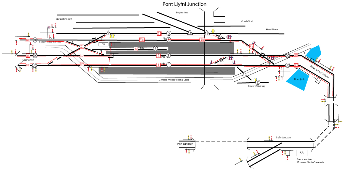 utton pairs, and will displays the DCC detected track circuits as well. The to/from buttons are shown as black circles, the LEDs for track circuit display as red squares with the detected area with a red line on the detected side of the track. Individual points that will be settable without a route setting are shown as black triangles.
Looking at circuit X1 is possibly instructive. It couples together a large number of drops because any occupancy of those tracks implies that all signals and points in the vicinity should be locked. The individual points are not hand settable because any move through that trackwork should be from one line to another – no smaller moves make sense.
