PDL Storage Yard
As important to the operation of a model railway as the elements you see is one that you are not supposed to care much about as a spectator – what happens to trains when they exit the modelled “scene”?
Just as with theatre, the area “off stage” plays a vital role in the success of the proceedings. It has to be able to receive and deliver a set of trains in a different order, and store them while they are not in the action. And, just as with theatres, space is a limited commodity backstage so order and design is essential.
For “round and round” layouts the work of designing backstage is simple or non-existent – there is a hidden part of the loop that either stores trains or let them straight through. But for “out and back” things are more complex because the trains need to be reversed as well. Now if one is modelling modern image where nearly all trains are double-ended, fair enough. But our model is early 1960s, and as such we need to support steam and diesel loco-hauled trains. We do have some DMU traffic which does not need to be reversed – so we can use simple dead-end sidings for that.
Problem
We need to simulate the Rest of the World (RoW) for our “out and back” layout with multiple entrances and exits allowing for long trains without taking too much useful area. The operation should be automated to the maximum extent possible because operating a fiddle/storage yard is very meticulous and also pretty boring work.
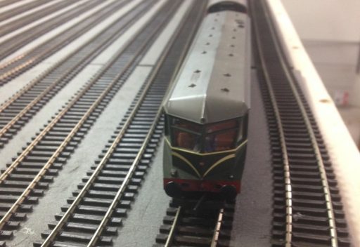
Trains should emerge in correct sequence with the loco facing the correct way….
In our design we have a total of a 20’x12’ space – but we wish to run up to 6 coach trains double-headed – or 7 single headed – in other words, we need room for 6 ft or even 7 ft long trains.
We also need enough track to store a large number of trains. Port Dinllaen is modelled on Holyhead and one characteristic of that station from its earliest days until the 1970s was the “tidal flow” of trains to meet the boats. Large numbers of trains would arrive to get passengers to the boats to Ireland one after another, and then there would be large numbers of trains to take arriving passengers away. The signalmen of the time reported that sometimes every block back from or up to the Britannia Bridge was occupied! This implies that there has to be room to store the trains that make up the peak flow as well as provide variety for the rest of the system.
Placement of the Yard
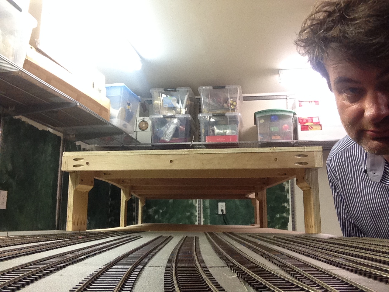
The first decision was that the area dedicated to the yard should be minimized. That is, it shouldn’t take up too much dedicated room. And that meant using “vertical space” as planners say – the are above or below the modelled layout. Below is preferred because it enables the yard to be placed only a few inches down – “up” would involve 18-24″. Getting from one level to another is much easier if you have to go 6″ than 24!!
Design Options Considered
Storage Yard
For “round-and-round” layouts this is a classic ladder design with sets of parallel tracks that can store trains. It very simple and can be highly automated. It does not reverse trains. The two flavours are a “through yard” where the trains enter and exit from opposite ends and the blind yard where they reverse in the yard and go back out the way they came in. A weakness with this approach is that there is a point of congestion at the entrance and exit which may slow down the ability to move trains in quick succession across all the entrance and exit tracks. The way to fix that is to add “staging sidings” at the entrance which allow there to be a number of trains stacked up ready to go for peak demand.
Vertical Traverser
In this design a set of cassettes is arranged in a vertical lift that moves up and down. The space used is therefore thin horizontally, but tall vertically. The limit here is how many levels of trains can be accommodated in the roughly 4 feet available above or below the track – roughly 8 or 9. Moving the traverser safely takes time. The traverser will only take a straight section of space as long as the longest train (7 ft in our case) and as wide as the number of train on each “shelf”. It is certainly possible to automate the vertical movement with some work. But it does not independently reverse trains – the cassettes or the trains within them will need to be manually handled to reverse them.
Fiddle Yard
The classic fiddle-yard requires an operator to move rolling stock around to reverse trains. In the simplest version they need to move the engine to the other end of trains by hand, which implies the yard must be open above over at least the ends of the entire storage space for the shortest and the longest trains which in practice means over most of its size (roughly 7’x4’). It will need a throat of points to get the tracks into the sidings – adding to its length. A rough estimate is that a three-way point takes 1’ so 9 sidings need at least a 3’ throat. Some designs incorporate a run-around track which will need another similar throat at the other end of the sidings. If that is all that is provided, the locos will re-emerge from the yard “backwards”. To counter that effect, one can have an engine turntable instead of one throat. It is difficult but not impossible to automate the uncoupling, engine turning and running around required, but, in reality the fiddle yard will need a human to supervise it.
Sector Plate
In a sector plate design the need for a throat for the yard is eliminated because the table pivots about a hub, or moves orthogonally to the tracks to allow different sector tracks to line up with input/output tracks. There are super-sophisticated versions of this design on YouTube that incorporate a horizontal traverser driven by stepper motors. The plate is about the length of the longest train which is good because no throat is needed. But this design does not inherently reverse trains.
Train Turntable
The classic Peter Denny design – which he called “my modest contribution to the hobby”. The sector plate is made into a turntable that can rotate through a full 360. In this way trains are reversed. PD did have a throat on his main Buckingham layout to enable trains to reach the different roads without moving the turntable (although when he went to exhibitions with the sub-layout, Leighton Buzzard, he eliminated that).
The turntable diameter needs to be as long as your longest trains (7’ in our case – his was 5’ because he was modelling Edwardian trains). And, to allow for rotation, the entire area of the sweep of the turntable needs to be kept clear as well. I spent a lot of time researching automation of this approach – given that it does reverse trains, it would therefore be a serious contender. But ultimately that need to have an area clear plus the sheer engineering of a heavy, long turntable which would need to be unsupported at the ends and so have to have a very stiff rotational point – like a car wheel axle – as it rotated doomed this idea.
Reversing Loop
It was not until I looked at reversing loop space requirements that it struck me – a reversing loop needs less area kept free than a turntable if it uses a 24” minimum radius curve -> 4 ft diameter and does so regardless of train length! This is why they are so popular in the States where 10’ to 20’ model trains are not uncommon. You do have to have the length of the longest train plus throats though.
Final design
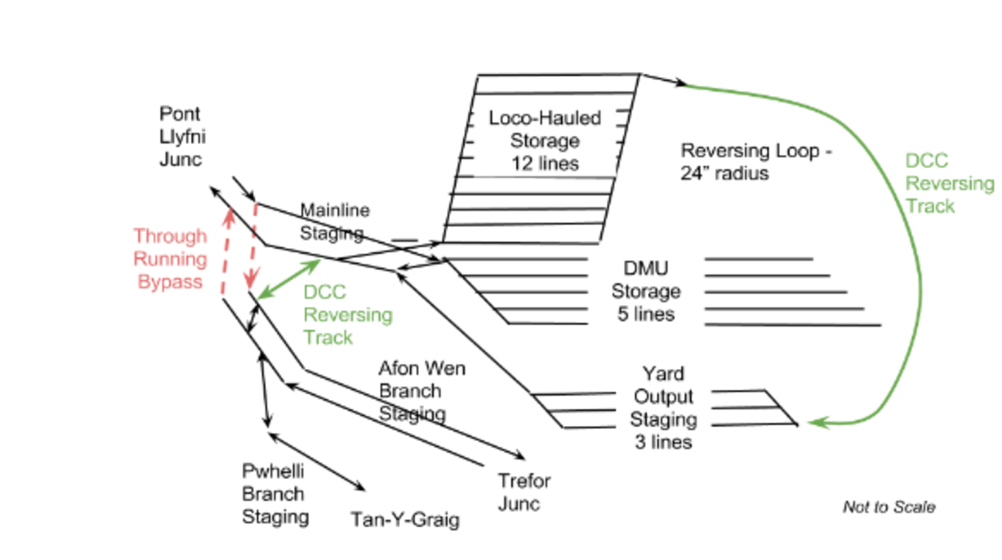
In the final design for PDL storage/fiddle yard I combined several elements –
- A 24″ radius reversing loop,
- a through storage yard with 14 roads of varying lengths for loco hauled trains of up to 7 ft in length
- a blind 5 road storage yard with 5 roads for DMUs and auto-coach trains,
- and several sets of staging sidings whose purpose will be explained later.
Loco-hauled trains enter the storage yard. Before they are required to leave they go via the reversing loop to the output staging sidings. If the train is a DMU it will be placed into the blind DMU storage and merely reverse out when wanted as the exit is in parallel with the staging.
The throat for both storage yards is combined with that for the exit of the staging sidings in such a way that entrance and exit can be simultaneous from the main line to and from PLJ. Entrance and exit from the branches (Pwllheli and Afon Wen) is single “threaded” but is buffered by each of these lines having a hidden remote staging track of their own so that by stacking up trains in staging 2 or 3 trains can arrive “on scene” simultaneously (mainline to PLJ, Afon Wen to Trefor, optional to Tan-Y-Graig on the branch) even while 2 or 3 are making an exit (mainline from PLJ, Trefor to Afon Wen, optional from Tan-Y-Graig on the branch).
Tan-Y-Graig is a single line, so the either/or option is implicit, of course!
Meanwhile another train can be in the output staging, up to 5 more in the DMU storage ready to go and one more moving from storage into staging. There is also the option for the train from Afon Wen or the TYG branch to go into the bypass which is itself another staging track and be ready to emerge to PLJ.
That ability to engender a sudden wave of traffic when combined with trains from PD and N should be able to keep the signalman at PLJ really hopping!
The whole yard is placed under the PD Station, enabling an almost 0% of floor space to be exclusive to the yard!
Through Running
The opportunity was taken to allow through running. This enables completely non-prototypical moves since the entrances to the staging are supposed to be 30 miles apart and in almost opposite directions!
It turned out, however, that this was a useful property for the Afon Wen line, since it allows a single train to simulate the series of trains in one direction to and from the Butlins holiday camp. In the real world, those trains would move campers out in the morning mainly to destinations in the Liverpool and Manchester areas, and then return with new campers in the afternoon. What we can do is hide the trains that have “gone to Afon Wen” in the through running loop and have them re-emerge as a new train on schedule “coming from Caernarvon” or vice versa.
More generally, for occasions where we want to run a train in or have some trains running with no fuss, it will be handy to leave them looping around between the Afon Wen line and the Caernarvon line. To do this the exit from the staging is turned into a triangular “wye” via the through running lines marked in red in the diagram. The Down line wye track is long enough to be a extra staging track as well.
DCC Considerations
This design needs two reversing sections to keep DCC happy (colored in green). One is the reversing loop itself which is about as long as the longest train when we add the points at the start of the staging. The other is one side of the wye – which is only longer than the maximum power consist – 2 locos. This means that the auto-reverser (PSX-AR) will get a good work-out in particular if we send one of the DMUs which have power cars at both ends (like the 6 car Midland Pullman) out on the branch. We shall see how that goes.
RFID
A problem that an operator (computer or human) of a staging yard has is the other operators. They can send trains out of order, they can add or delete engines and rolling stock and so forth. This becomes very important to the successful management of the yard since putting a short train into a long siding can block a future train and the other way around can spell big trouble as it will block some part of the yard.
What we need is an equivalent of the human eyeball Mk1 – and that seems to be RFID. It is a technology used by the 1::1 scale railways, in fact.
By positioning RFID readers under the remote end of each entrance track and having chips on each wagon/coach and engine, we can read the train contents and length as it is sent into the yard, with enough time to pick a good siding for it based on length and type.
A further advantage is that knowing the current makeup of good trains would enable waybills to be constructed that the PLJ marshalling yard shunters can use to make up trains for the different destinations. This would work even if the station operators fall down on the job and fail to send, or send different wagons to the storage sidings.
Progress

