My son, Spencer, had chosen a science project of rating bridge designs on their load-bearing capacity. He picked three, the trestle, beam (box girder), truss and suspension. A few dollars worth of basswood later…
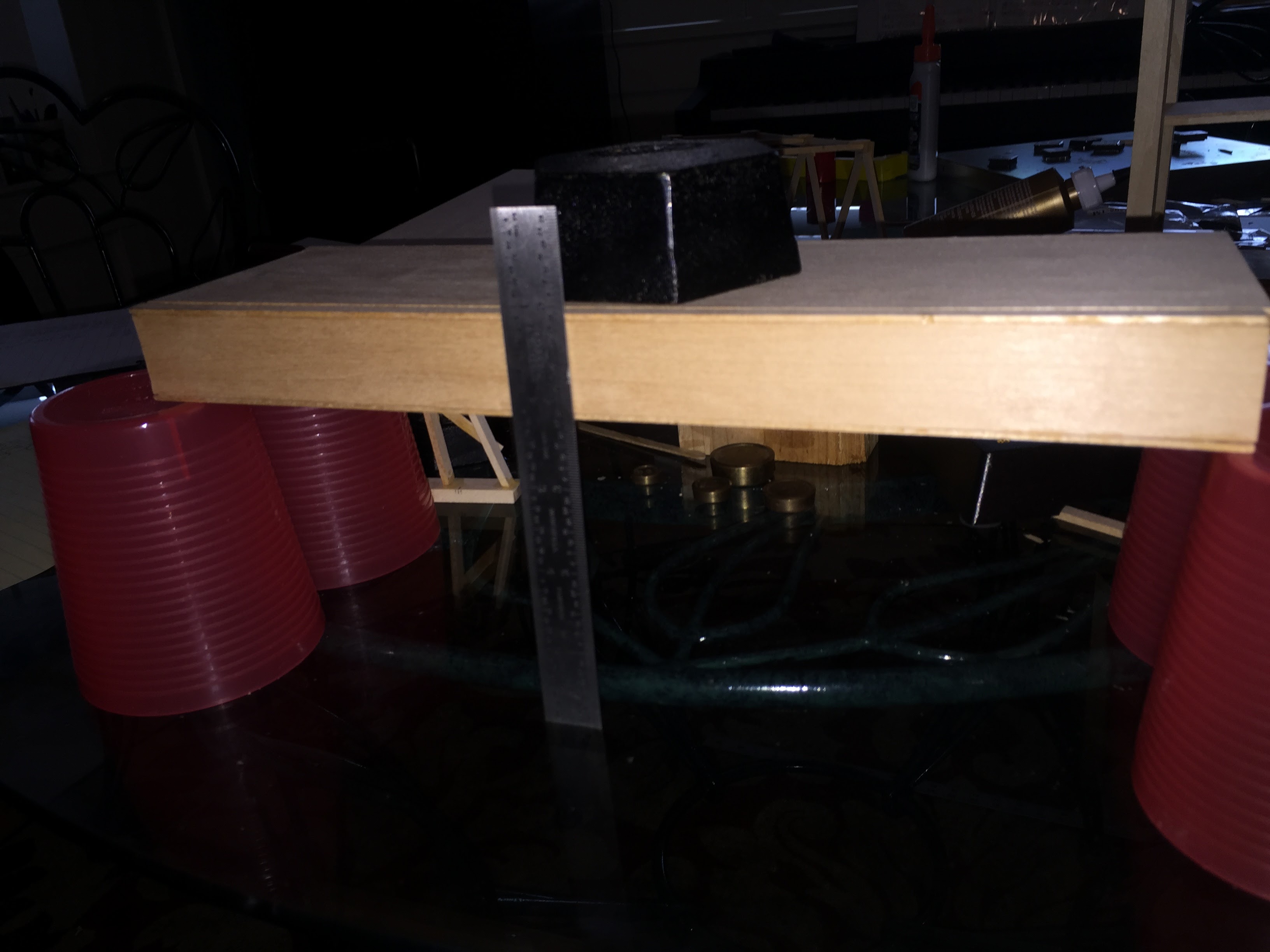
Beam –
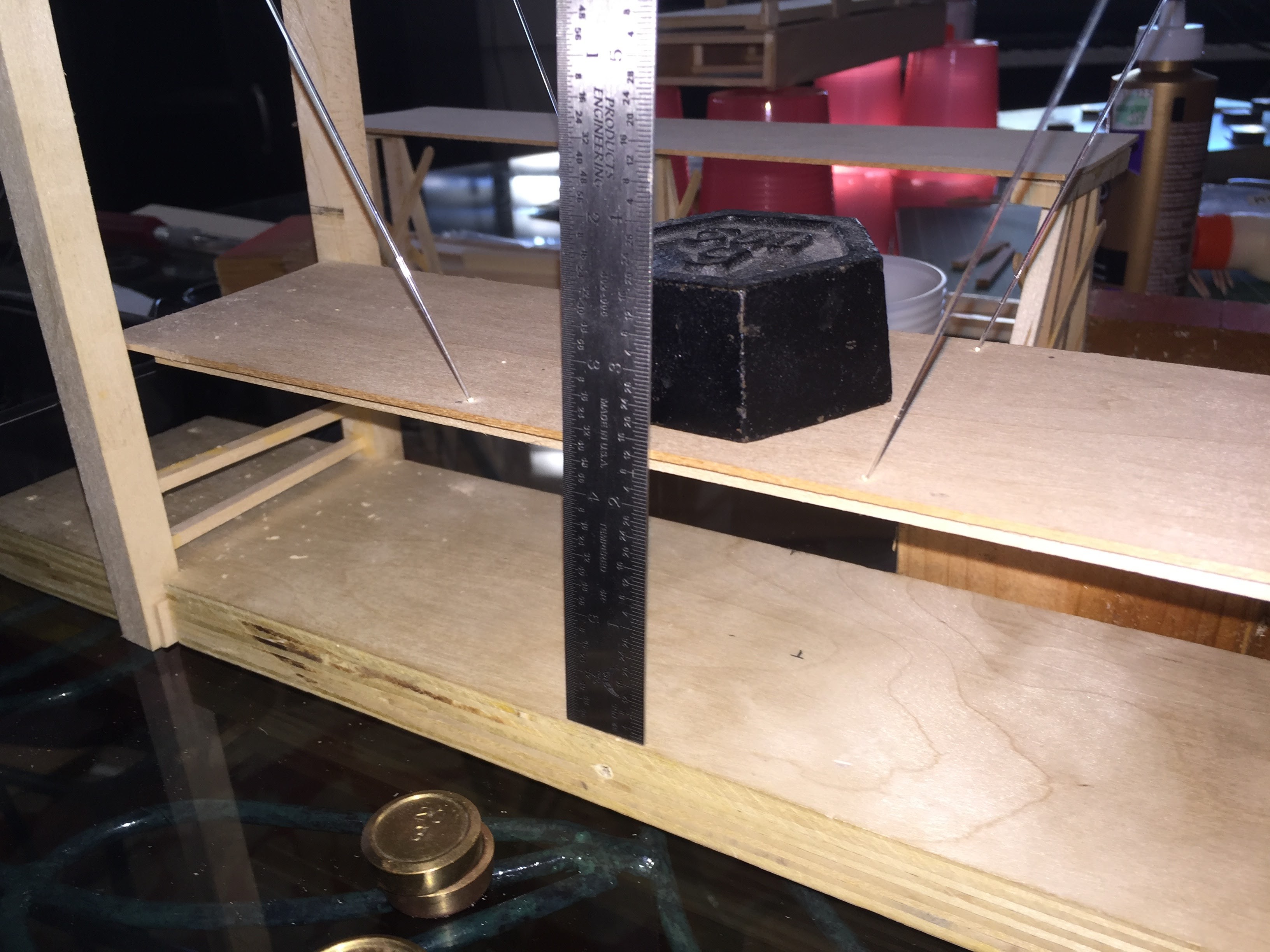
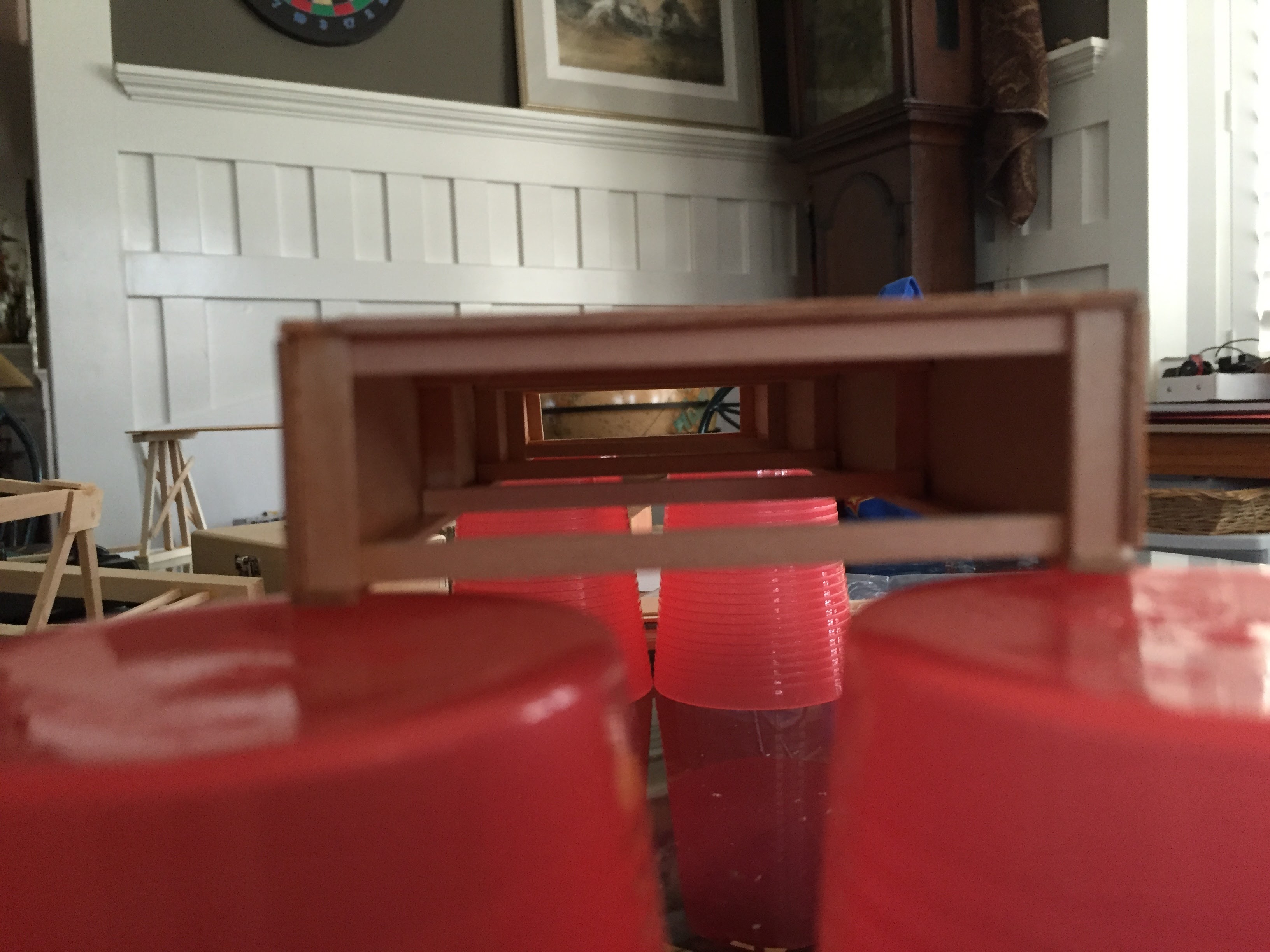
This started out as a plate girder but morphed into a box. Had it got taller, it could have become a tubular bridge – like the Menai. Impressive performance under load – no deflection seen with a load of 2kg at the center of a 12″ span.
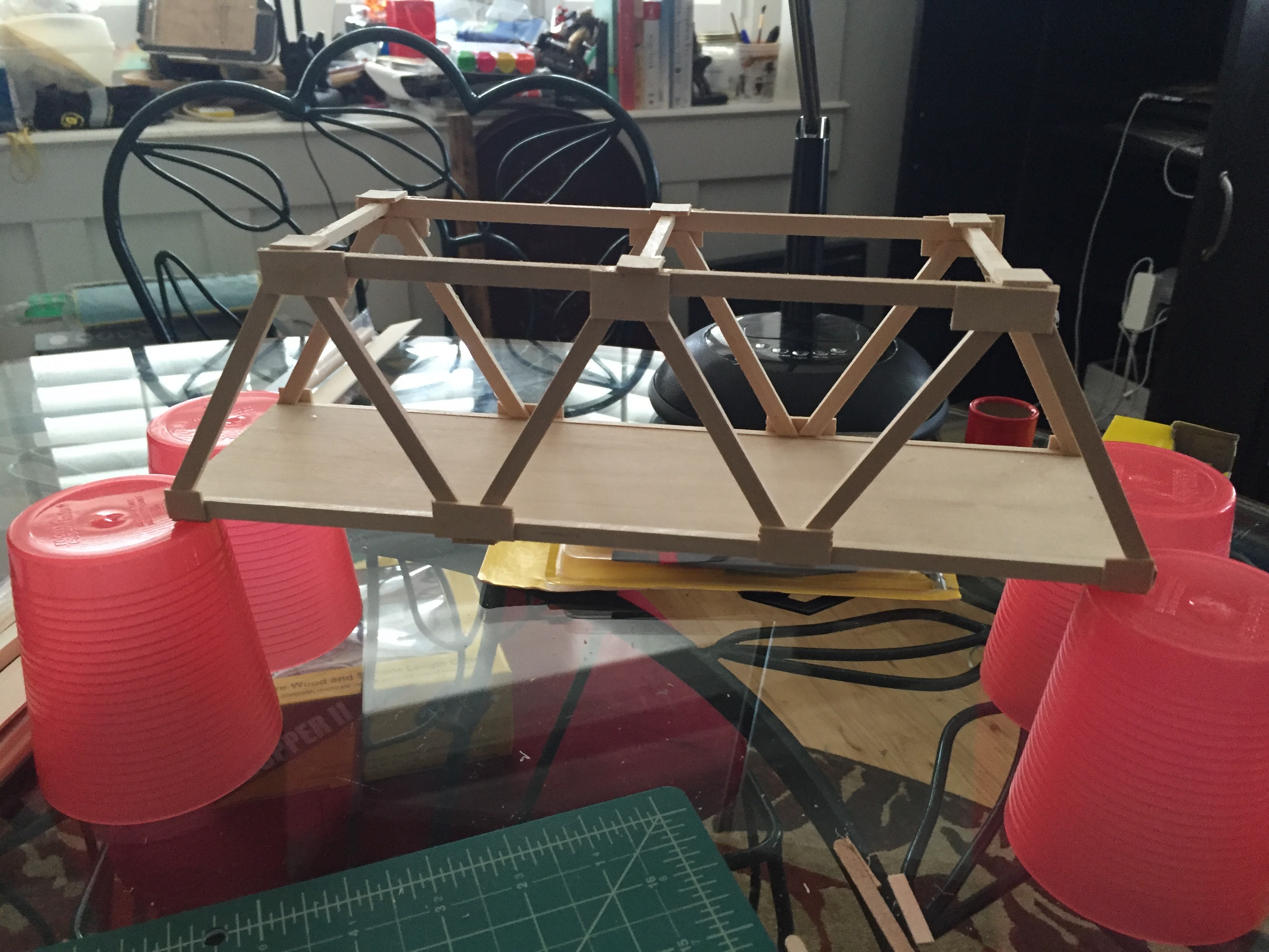
Truss –
Next was the truss – which had more but still no a lot of deflection.
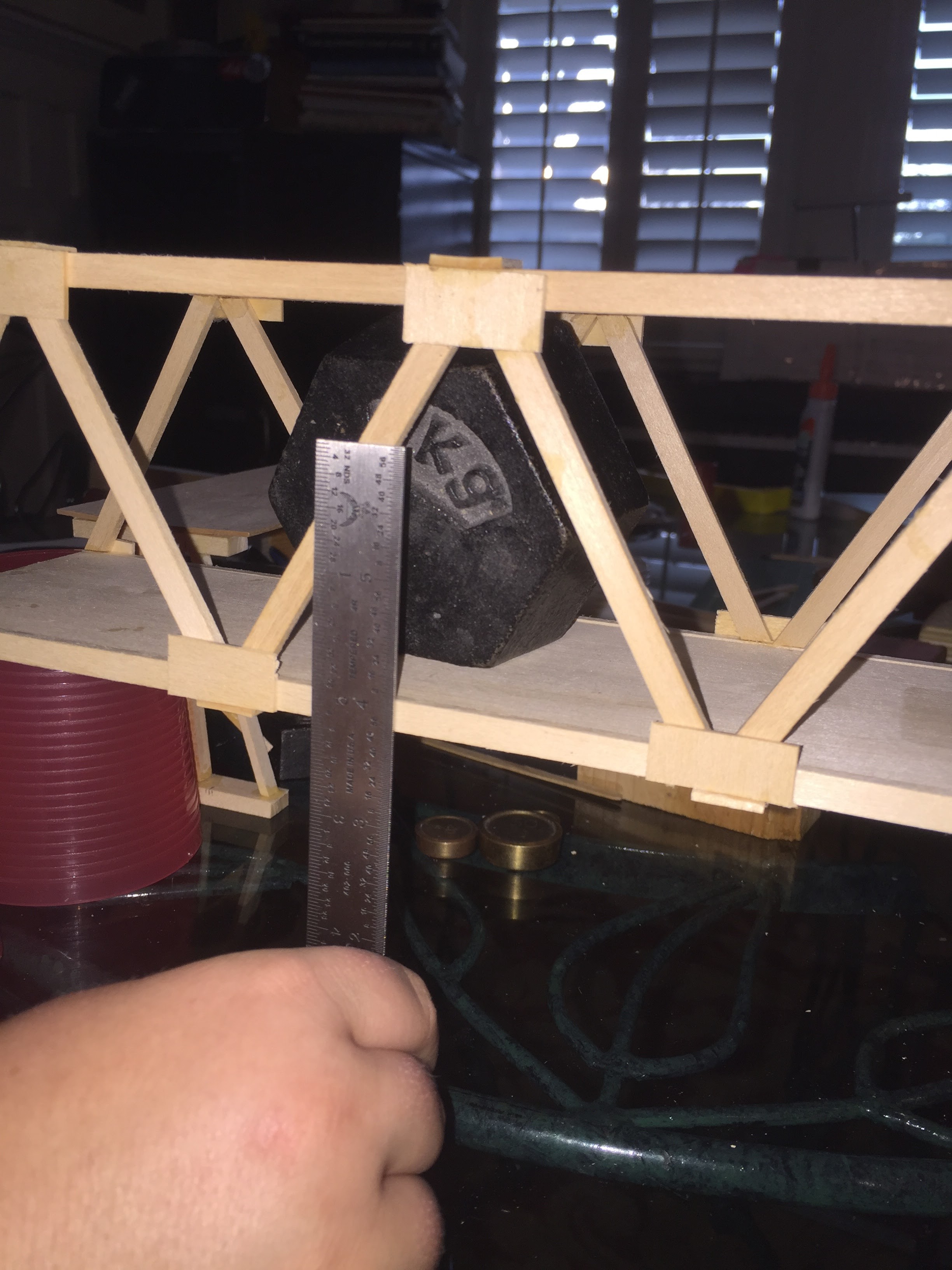
Trestle –
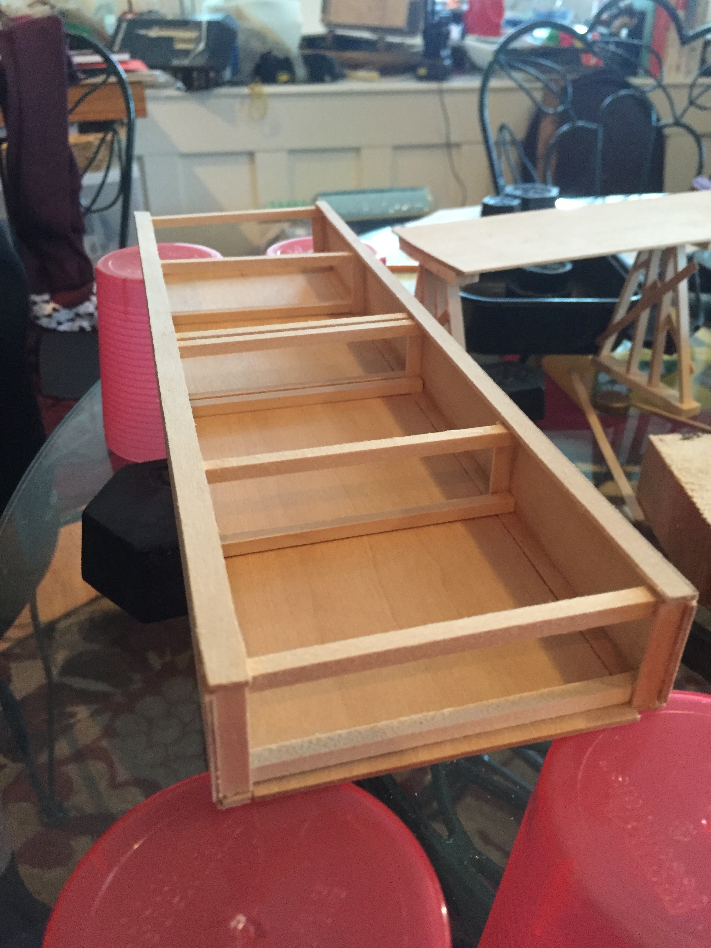
The trestle was his favorite for being strongest before the test, but, of course, even though it has more supports, the load is being taken by a thin plate and so the point load will eventually cause a sag
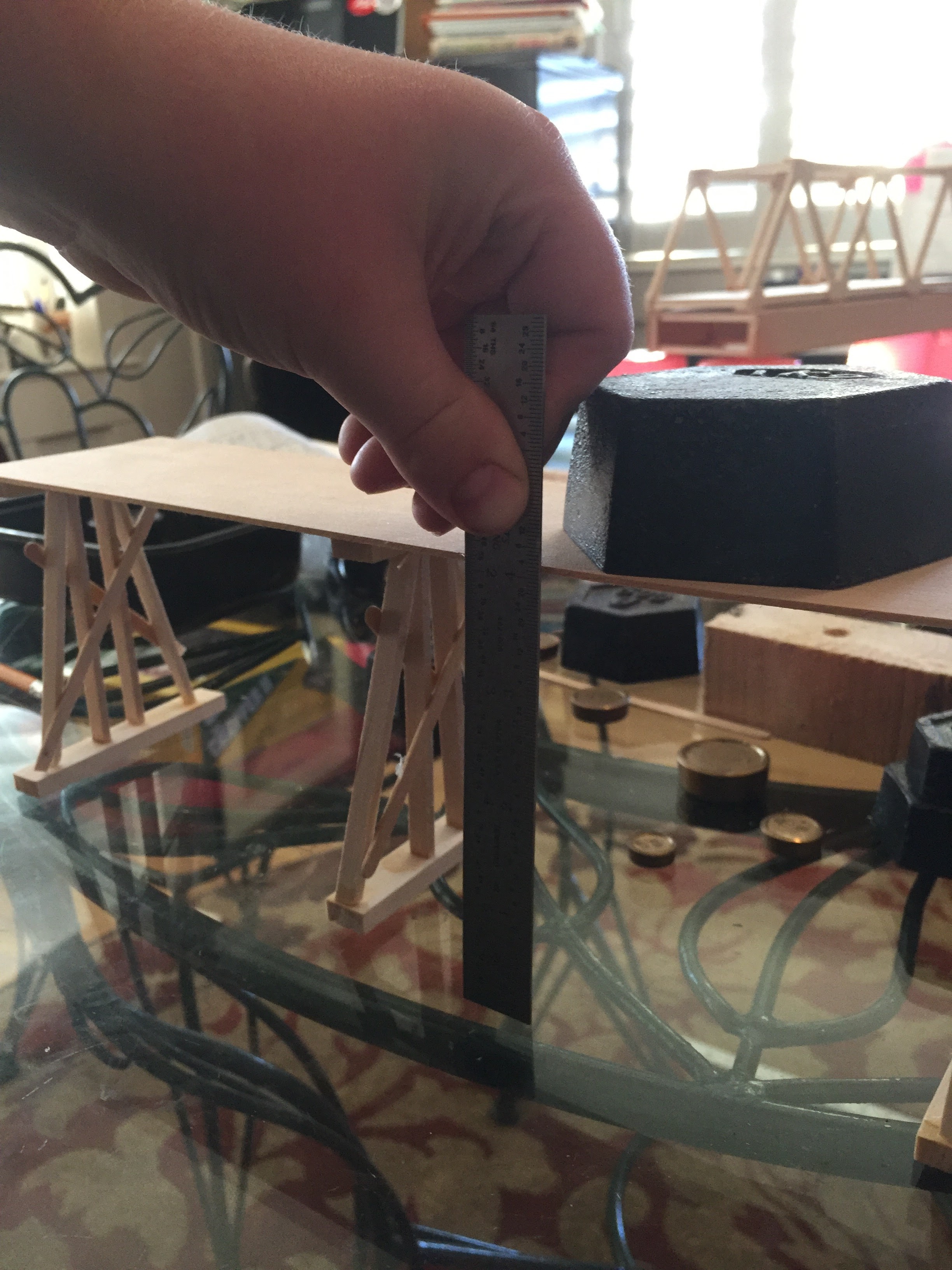
Suspension –
The suspension bridge, of course relies on the strength of the cables. Spenser opted for a single-cable suspension bridge that takes all the load on a cable from a single point. Shortly after this picture was taken the “cable” gave way. I think he now knows why a railway on a suspension bridge only works if the deck is on of the more rigid shapes. Interestingly (which I did not know) the Britannia Bridge over the Menai Straits has the towers shaped as they are to enable suspension cables to be hung. During testing of the original design, it was determined that the box girder tubes were sufficiently rigid to not need the support.