 Module 3 of twelve is now in electrical order. I followed my pattern of two buses – one for the accessories (inc motors) and one for the track. I will eventually have a booster just for accessories. The track will be cut into sections so that boosters can be added later and those sections each will have a circuit breaker as well – so that short-circuit problems in one area don’t cut out other sections.
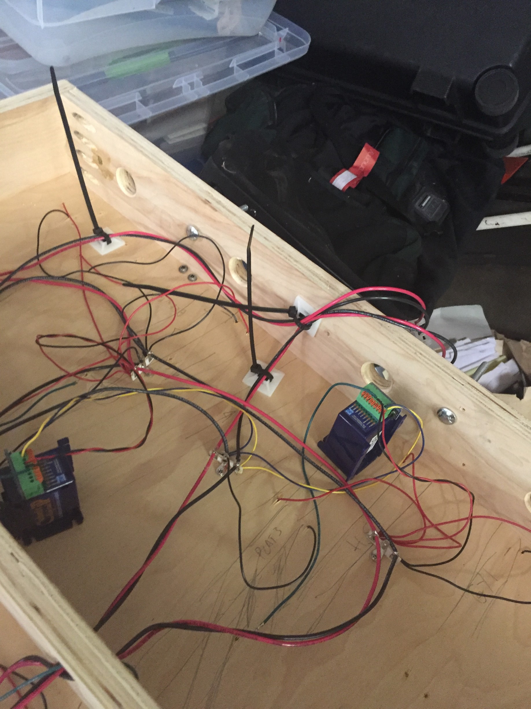
The first picture shows the downstream end with its flexible connection to the next module (which will be the section with the swing gate). The cable is loosely constrained by the zip ties to reduce the strain on the last connections.
Crossing the gap are the two distributions busses. The idea of having both is that the most common source or a short-circuit will be a wrongly set point – and having a separate supply to the point motors ensures we can clear that simply.
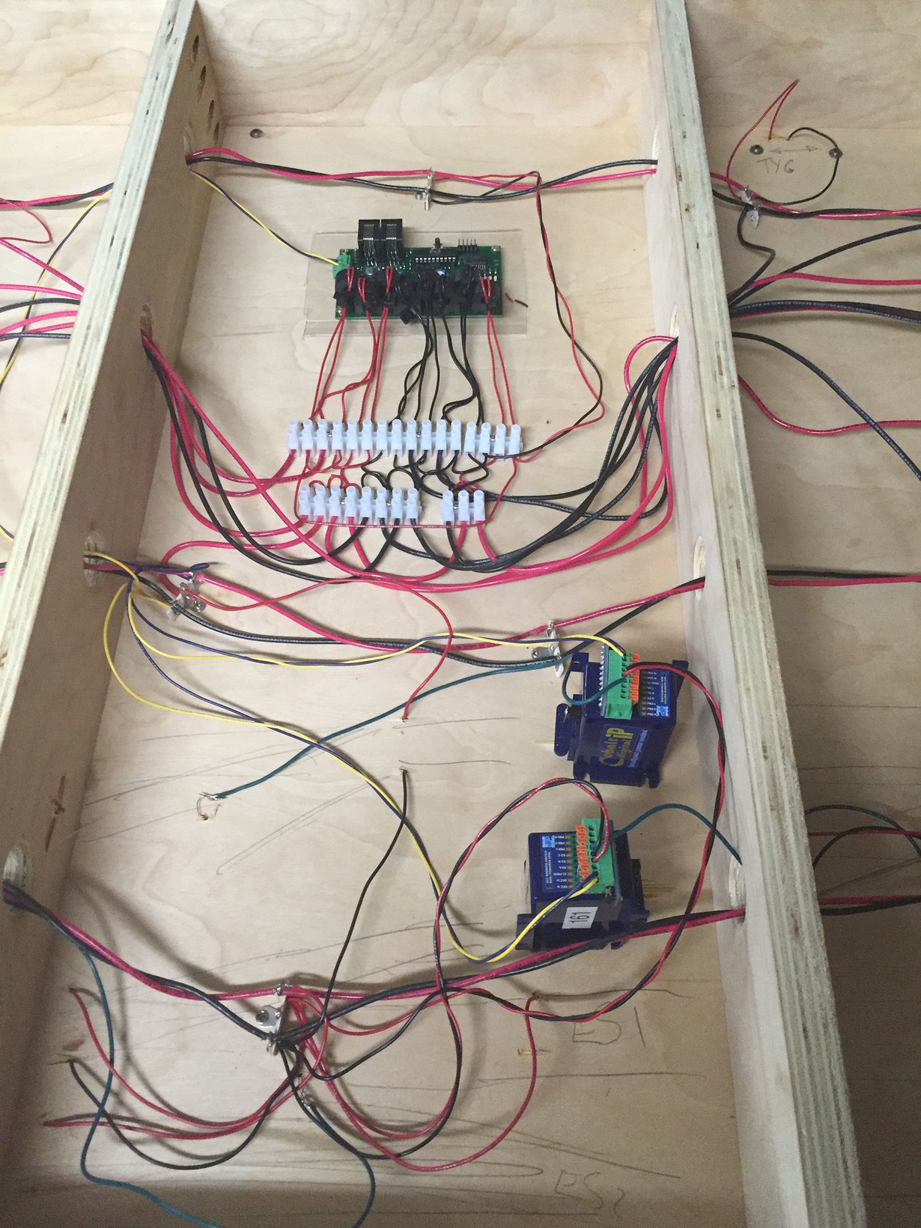
Color coding is yellow and blue supply the accessories with power, green goes to the point frogs, red and black are the buses and supplies to droppers and the point motor switches.
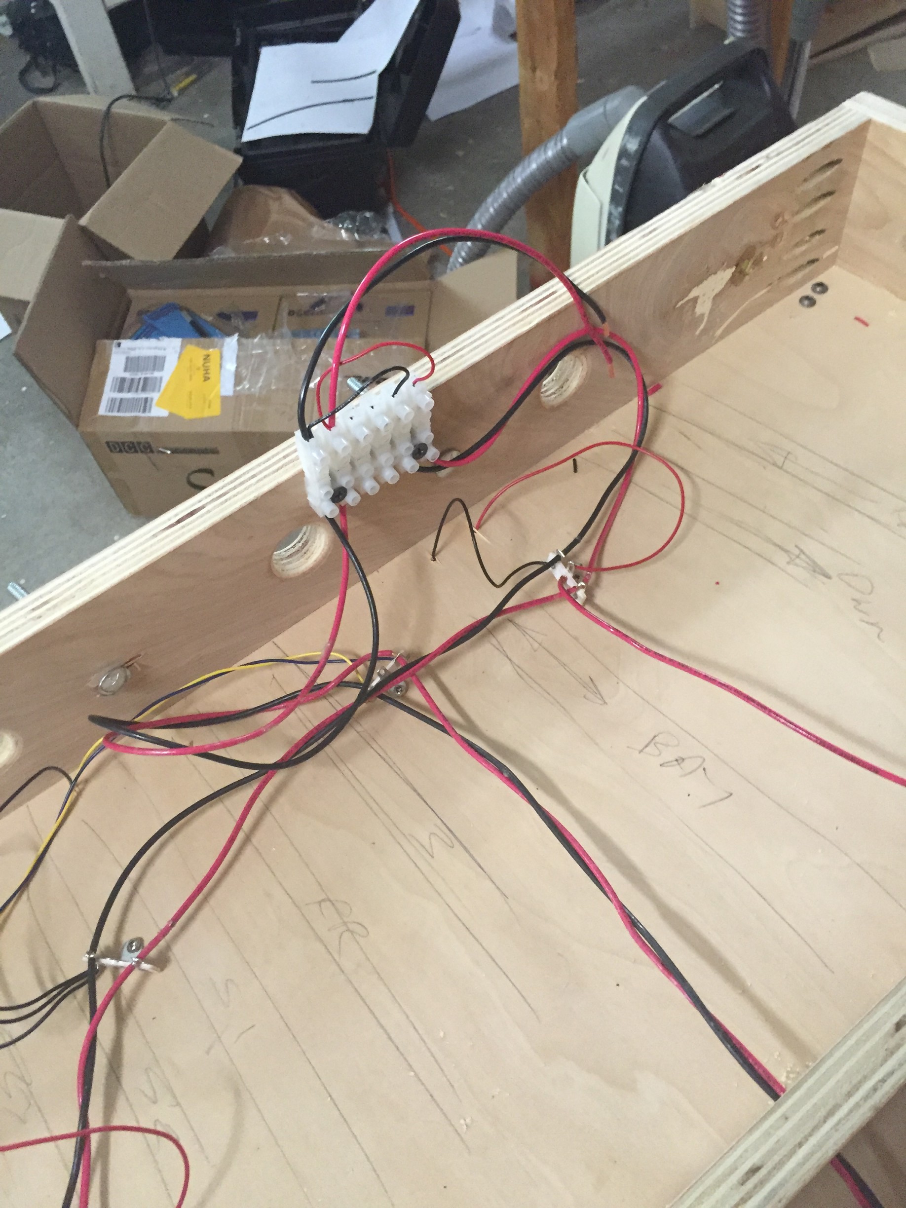 The second picture shows the upstream connection. Attached to it is the testing jumper which cross connects the two buses for testing.
The last picture shows the wiring for the BlocD8 occupancy detector. Each detected block or sub-block has a color-coded leg that comes to the detector via the euro-style “chocolate bar” connectors. The sub-blocks are ganged together and then passed twice around the on-board detecting toroid.