One of the misconceptions about DCC is the single pair wiring theory – that you should use just one pair of wires and you can run everything. Just so simple and in fact, it will work in strictly technical terms. But it is a BAD idea.
The biggest problem with it is the practical one of a short induced by wrongly set switches/points. If a loco approaches the “wrong” leg of an electrofrog switch, it will encounter the wrong polarity of DCC as it crosses over the Insulated Rail Joiner (ISL). This will cause a short, and the controller/circuit breaker will shut down. Murphy will dictate that this happens at the most inaccessible point on the layout!
It is vastly superior to wire the supply to the point motors on a separate circuit, using a dedicated breaker after the common feed for the track supply, so allowing the point to be reset and so the short eliminated. Therefore means two pairs of bus wire are needed at a minimum.
There are other reasons for additional Buses and wires as well
- Supplies to/from AutoReversers
- Block detection wires from the track to the sensors
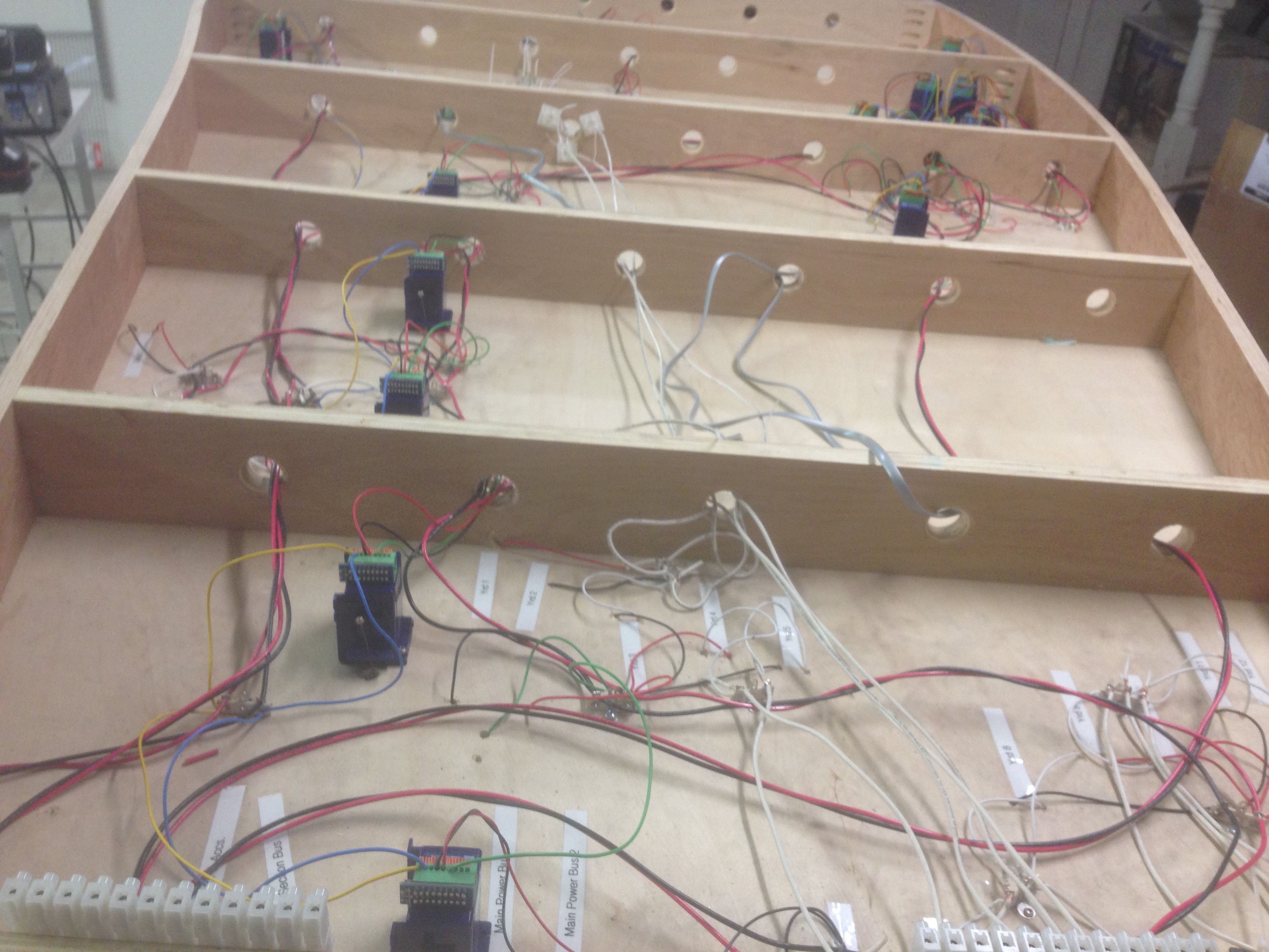
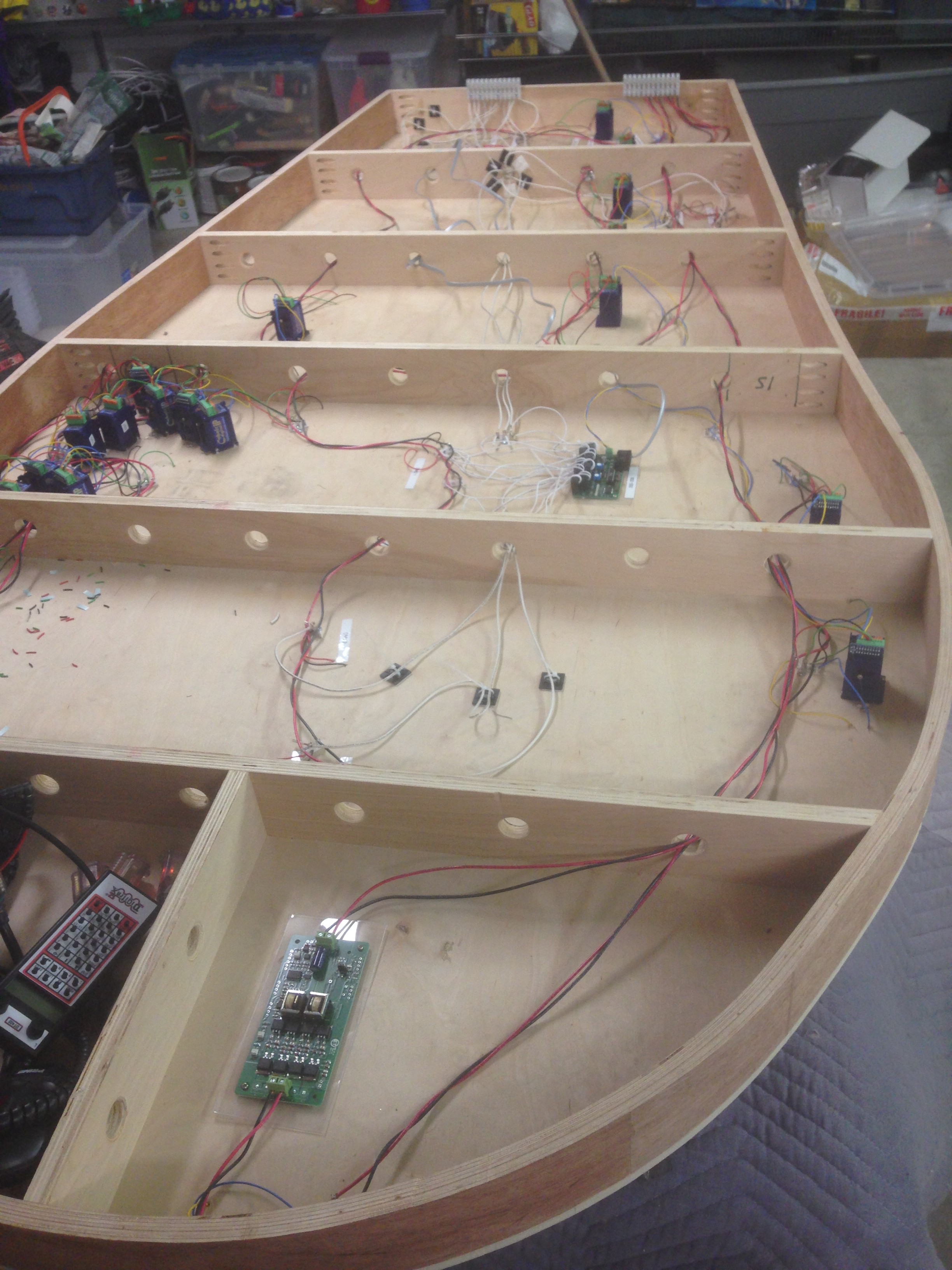
In this picture of the underside of the storage yard, the bus supplies and droppers to the rails are are red and black – the block detection circuits are white, supplies to the frogs of points are green, supplies to point motors (DCC Concepts Digital Cobalt) are yellow and blue. There is also a grey LocoNet cable. The buses are twisted together to reduce inductive loss. The wires are soldered together using bus tags supplied by DCC Concepts. All in all, a lot more complex than “just two wires”.
