With PD we expect to have a continuous flow of engines that need to be cared for at the end of a run and made ready for service quickly. A boat arrival/departure will generate at least 5 trains inbound within a short period and a similar number out. Some will be double headed as well. So we need an efficient layout – which is something that the LMR and LMS made a study of and introduced automation to starting in the 1920s.
PD is presumed to have benefitted from this in a way that Holyhead didn’t possibly under the joint pressure from the ER while it ran the ex-GC lines. It will have
- a coaling tower (sized as for Wick rather than Carnforth)
- an ash tower
- overhead sanding refill
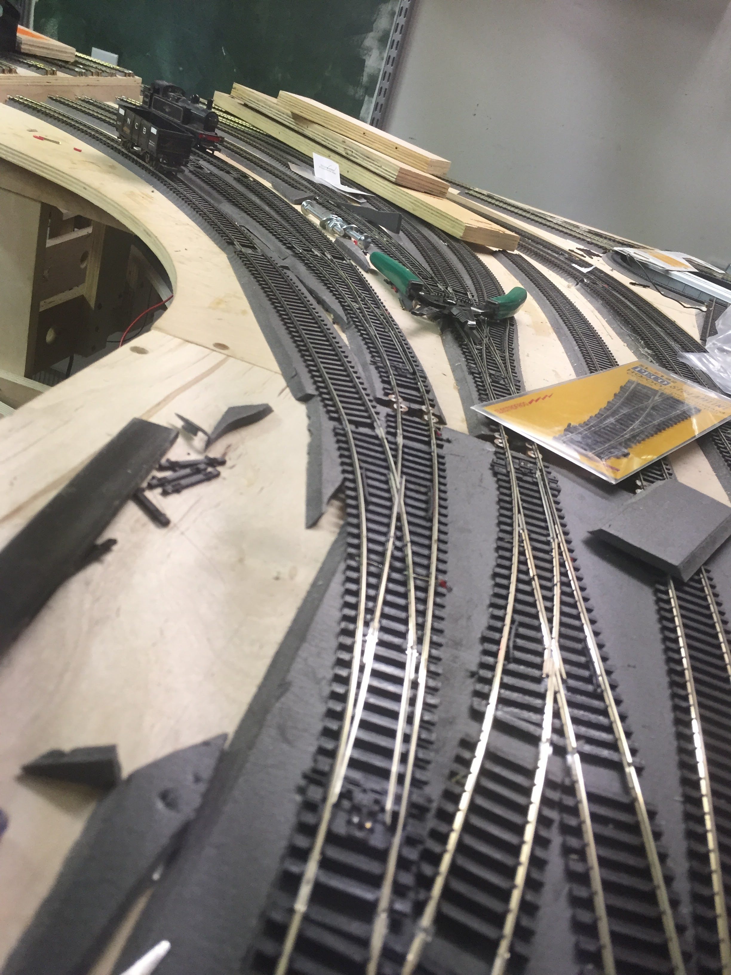
In looking at placing all these, I discovered that my first tracklaying in the MPD area had perverted the plan laid out in XtrkCAD and meant that the coaling road to the turntable and the bypass road was shorter than intended, reducing the area in which the ash and coal plants could be placed. Luckily fixing it was a simple surgery – moving the last point to be first and reattaching all the same sidings quickly added 9+ inches to the length of the two roads.
I did some research as to the order of things at real MPDs and found that while it varied often was coal (plus water), fire disposal (ash), turn, then go to shed. In non-mechanised plants (the majority) the sanding consisted of fireman making trips to the sandhouse with buckets so the order is undefined.
Given that my ash plant is bigger than my coal, this handily gives a visual break with a build up in front of the north-light shed and disguising the corner of the room slightly when standing in the MPD operating well.
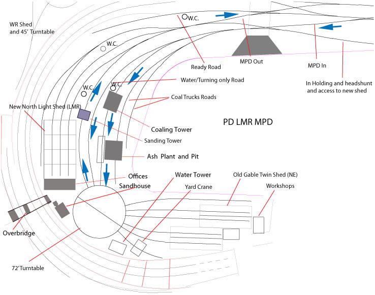
So here is a graphic of the flow in the MPD. I’m still debating the precise placement of the sander – it may be better nearer the sandhouse just at the turntable exit. That would also allow “the hand of God” to intervene with any stuck engines at the North Light shed.