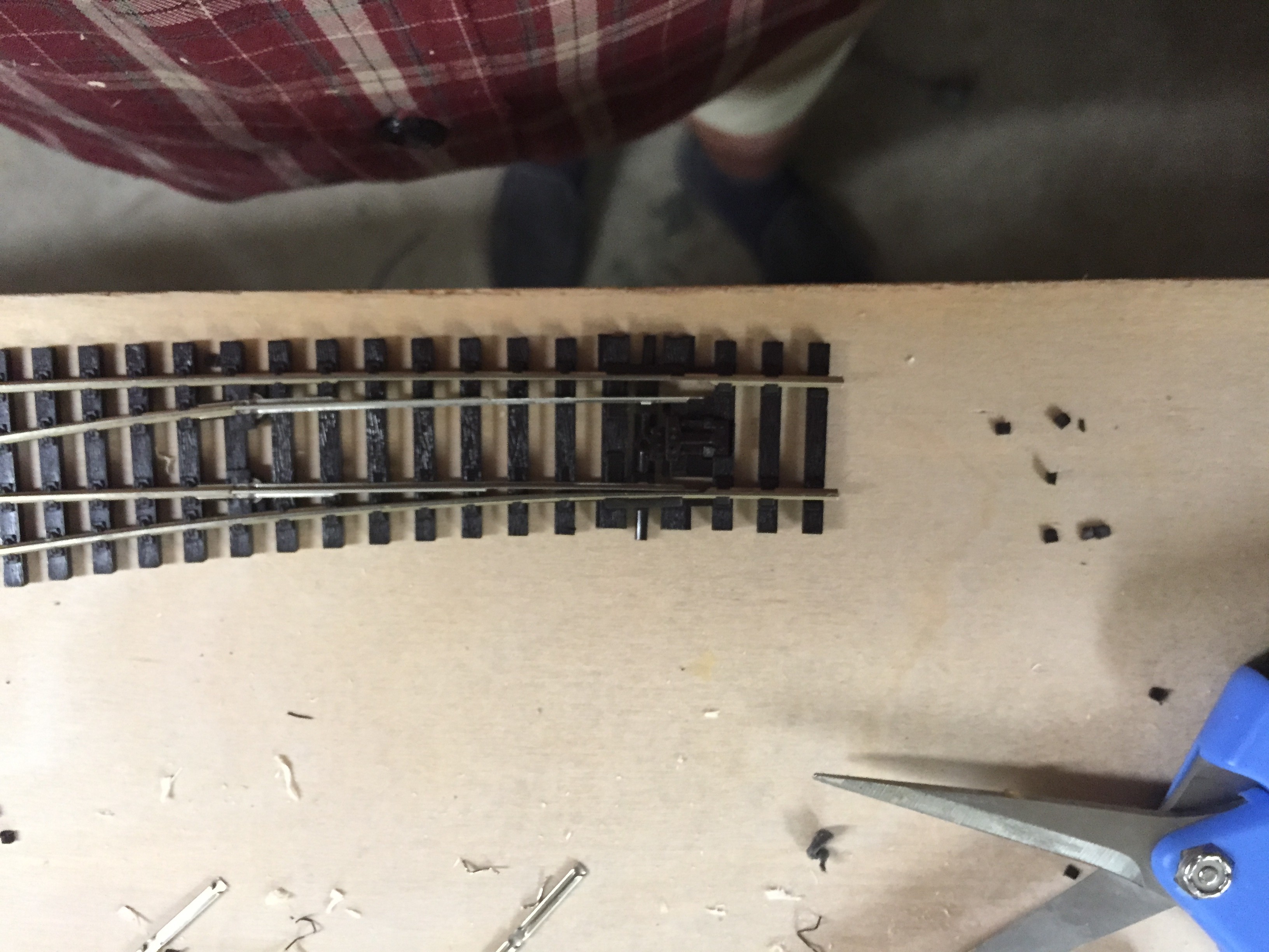
The points/switches are Peco code 75 Electrofrog. To prepare them for my used as DCC using stall motor (Cobalt) there are some details to be attended to.
First place the point on a flat surface – you will be using force and heat = and having a hard surface backing the point up will reduce the chance of damage.
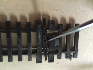
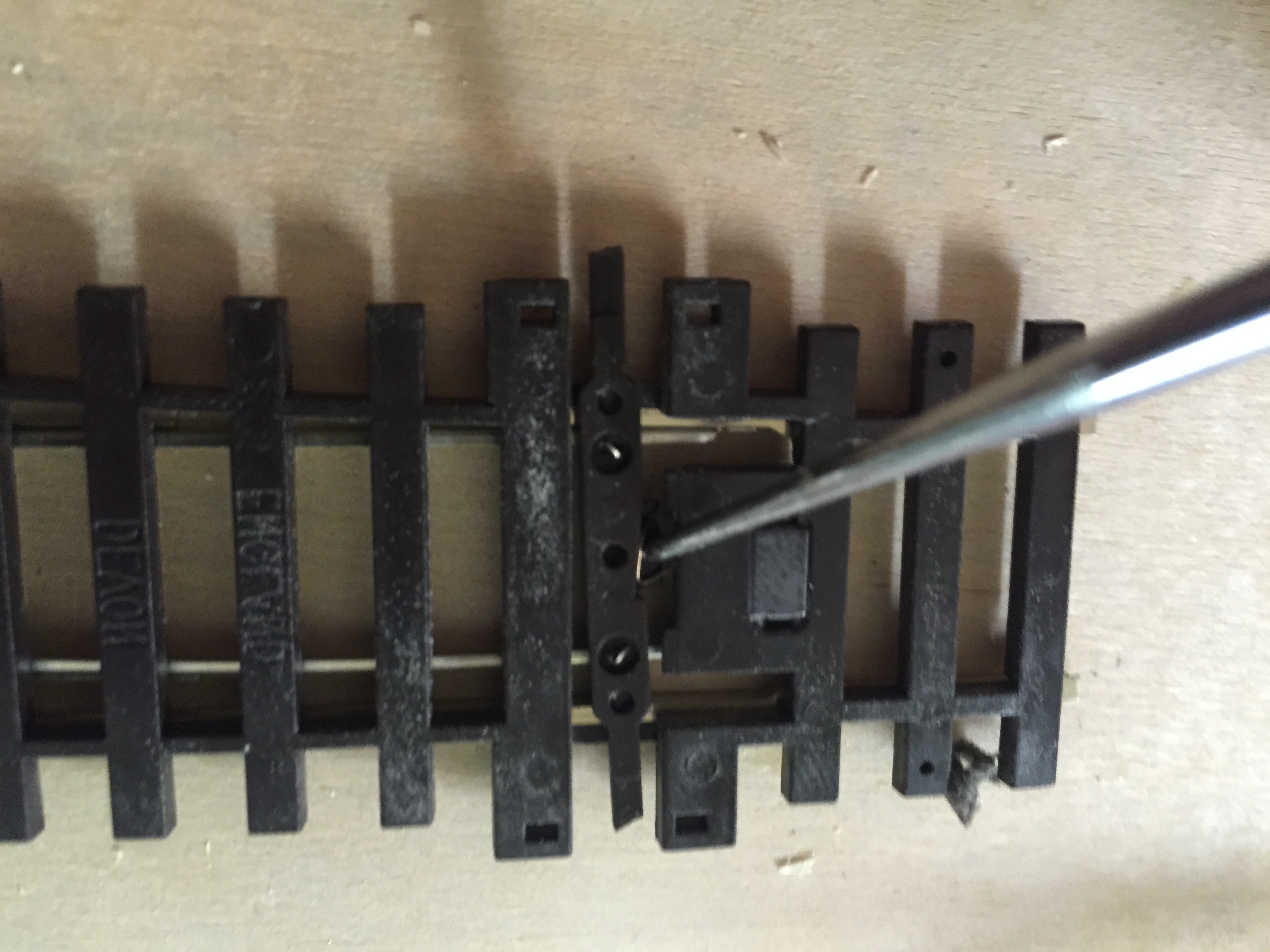
- The links between the diverging rails and the frog need to be removed/broken. (This is not needed on crossings or slips).
- The problem is these wires are buried deep in the plastic and were electro welded at the factory. Place the point upside down on a flat surface. I do this with a handy “pointed” tool like an awl and I place it as near to the weld as I can and try to move the wire – about 80% of the time a sharp “click” means the weld has broken. You can then try the other end. Sometimes the weld needs to have this process reversed.
- If you can only get one end’s weld to break, you can bend the wire up and then grasp the exposed end with snipe nosed pliers and “wiggle” until the other end fails… Given the popularity of DCC – this is something Peco could do well to offer as an option.
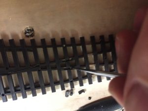
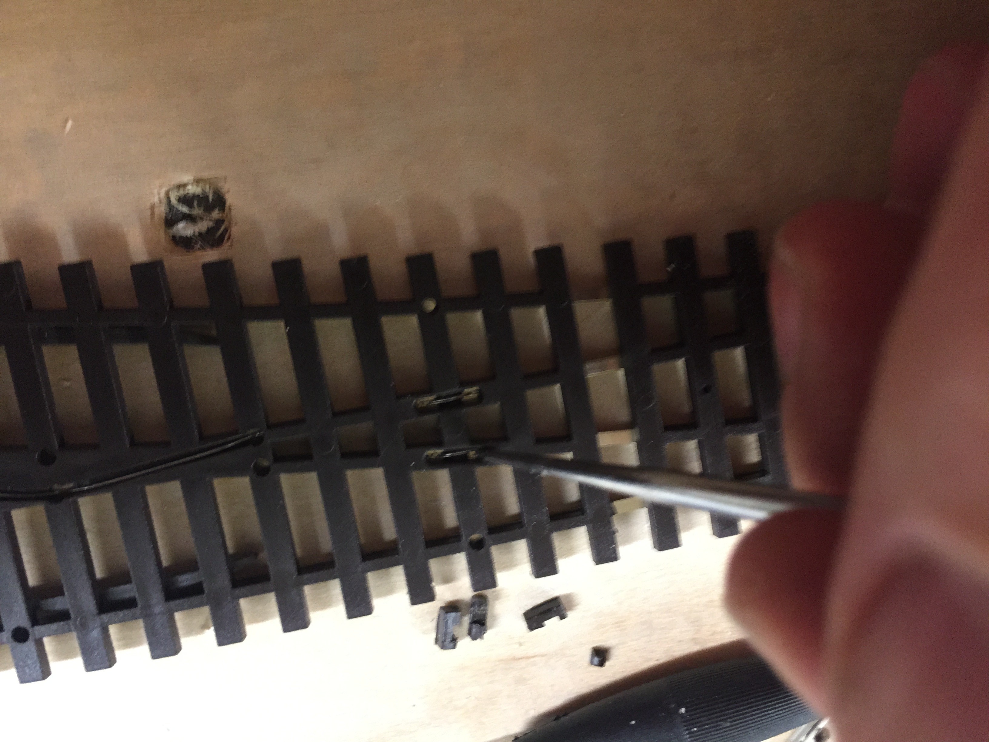
- Removing the spring that holds the tie-rod to one side or the other.Normal Point.
- To do this I move the tie rod to the end that exposes the spring the most. Then I put the awl under the spring and lever it up. After a little bit of give, one end of the spring will pop up. Next you grasp the exposed end with the snipe-nosed and pull it while twisting – the whole spring will come away.
- Slips. The spring is hidden inside a covered area. You must pull up the cover over the mechanism from the end that has the slot. Removing the spring/springs is them very easy – they will usually fly of and fall to earth somewhere remote!
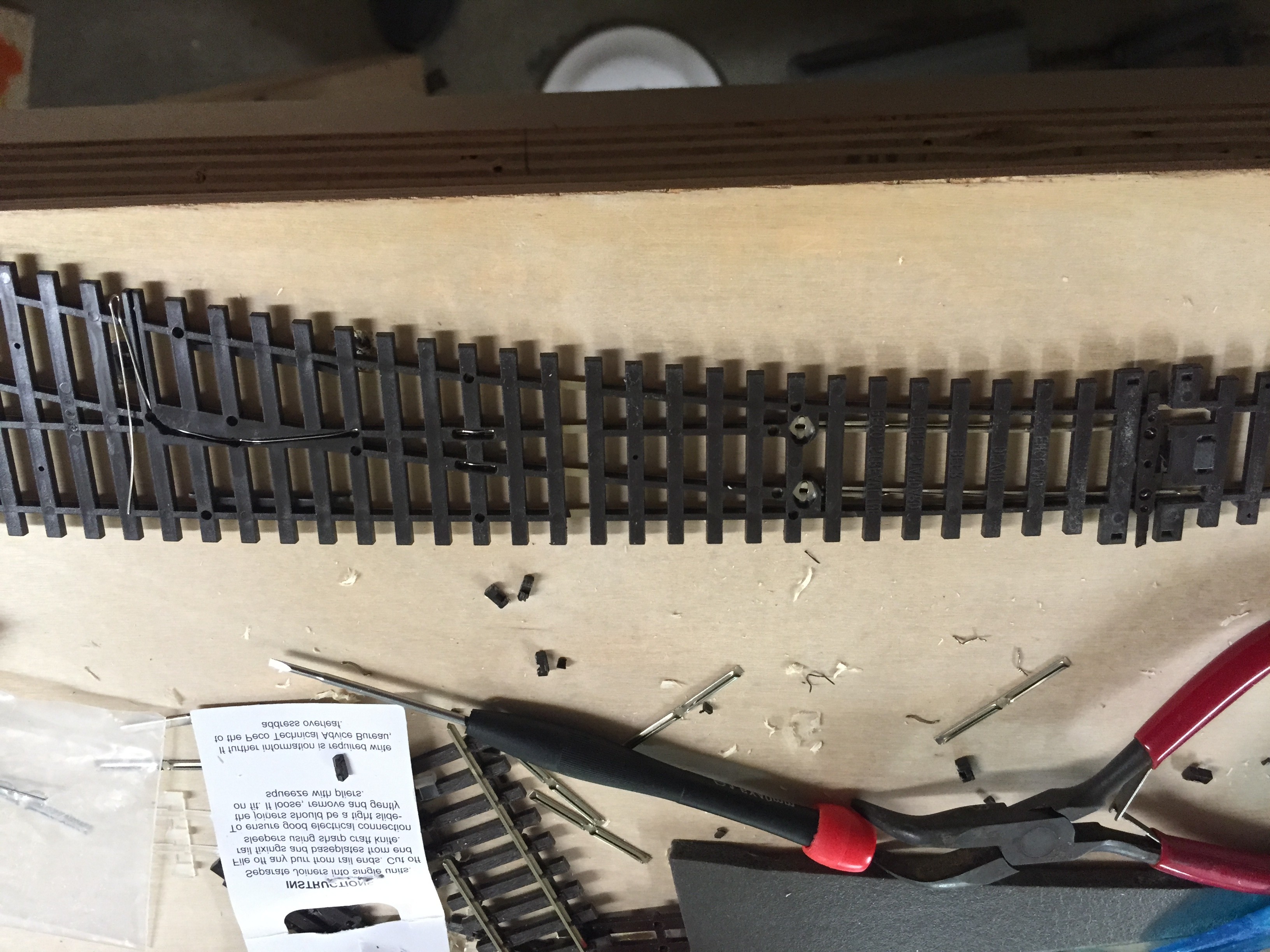
- Bonding the closure rails to the running lines. (Not needed on crossings or slips)
- I clean the excess plastic from both sides of this area with a craft knife (Xacto). This is because I want the area to be wide enough that my soldering iron will not touch the plastic while making the joints.
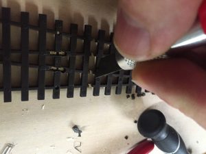
- You solder a wire across these points to electrically bond the rails to the track supplied with current on each side. Actually I now go further and use a dropper wire with an extra-long stripped end to bond these two rails, which also neatly powers the point and any rails that it is connected to. A twofer!
- I clean the excess plastic from both sides of this area with a craft knife (Xacto). This is because I want the area to be wide enough that my soldering iron will not touch the plastic while making the joints.
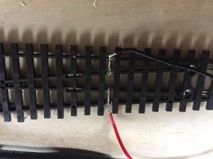
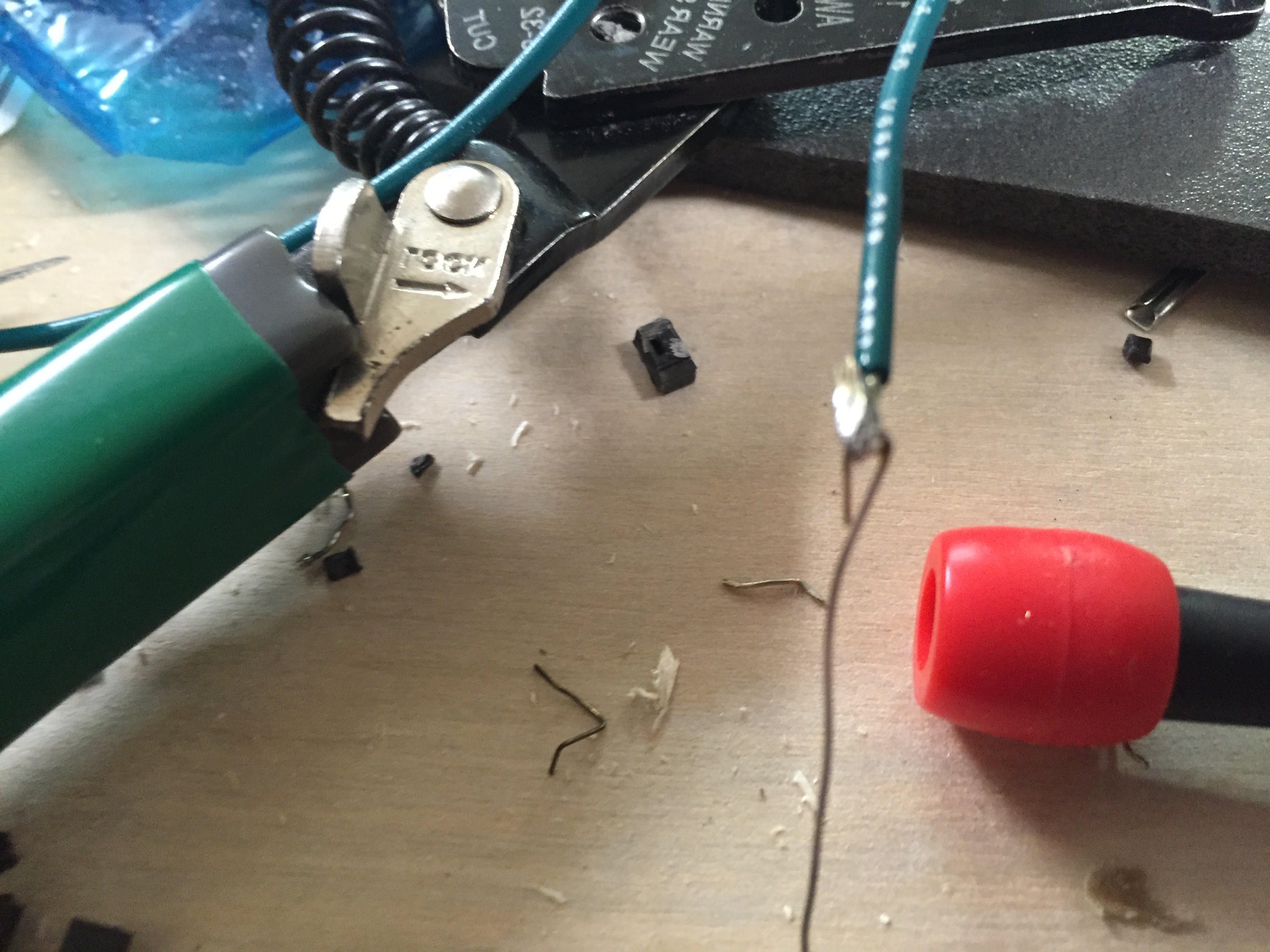
- Add a frog dropper wire to the frog wire.
- I have taken to letting the frog wire stay in its slot under the point and drilling a hole at the end of that sleeper rather than trying to estimate a direct drop from the frog. So I leave the frog wire on the frog and solder to the end of it.

- I have taken to letting the frog wire stay in its slot under the point and drilling a hole at the end of that sleeper rather than trying to estimate a direct drop from the frog. So I leave the frog wire on the frog and solder to the end of it.
- Test – using a multi-meter, ensure the closure rails are bonded to the outside rails, that the frog is isolated and supplied by the frog dropper, and that the outer rails are isolated from each other.


This sounds like a lot but with practice each point will take about 5 minutes to prepare.
The last step is to make the point look better cosmetically by performing some surgery on the tie-rod area. Using the plastic cutters/shears from DCC Concepts I cut away the “knobs” on the end of the tie-rod that are for above baseboard operation and I shear off the area designed to hold a Peco solenoid motor under the baseboard. 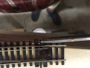
The result looks good enough to my mind… a purist would replace the whole tie rod area with new sleepers – the suggestion of a non-prototypical point motor and possibly facing point lock would be an anathema to them. As I am modelling a railway that used advanced techniques like LP pneumatics, it does not bother me – and also gives and excuse for the absence of point rodding…